DB verbosely concludes:
Day 2 of the ZH mini-saga involved sticking on the other three doors and finishing up. As you might have noticed from last time (pic 2 in the previous ZH edition), rather than fold the supplied two door etchings per wagon (one for each end) right over the top, I elected to cut each in (almost) half to make 4 seperate doors, discarding the central bit that represents the roof beam.
This was for many reasons - firstly, this kit is in 'beta' mode and this was my first attempt at it, secondly, I doubted my ability to make all the folds perfectly all the way around the wagon (to match the crosswise formers they would be glued onto) , and thirdly I'm sure by the time I finished applying plastic cement to all those formers and surfaces that need to be glued, most of it would have set already.
To ease the door folding process, it is important that they be carefully scored along the supplied lines, which is tricky without going through the thin material or scoring folds so thin that they split when folded - ask for a spare and use a blunt knife! The score line intervals must also
match between the various doors (there is some judgement required here as the lines are fairly thick) to get a pair of doors that match in their complex profile for each side. However if you do all this and then fold it up a little more tightly than needed, everything slots into place like magic and the whole door-attaching exercise ends up being less stressful than expected.
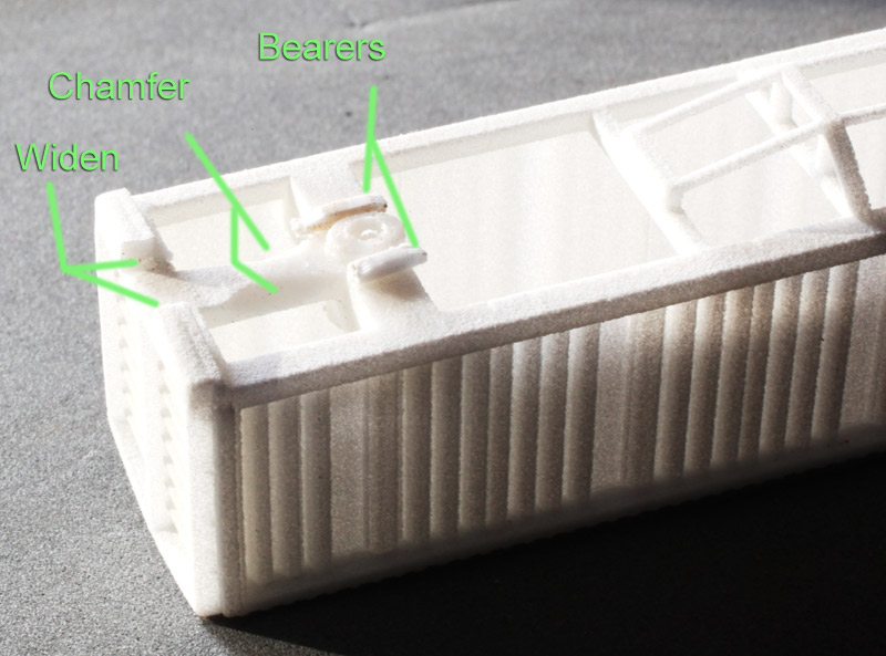
If you go this 4-door route, you then have to rebuild the top roof beam (the discarded middle section of the door etch) out of plastic strip, but as long as you remove any protrusions on top of the crosswise formers, you'll have a nice straight line along the top of the main lengthwise bulkhead to base this on, something I didn't have with the ZG and thus things went a bit wavy on that one.
As it turns out, I have ended up with a nice model, the only glitch being a tiny bit of glue melt right in the middle of one of the doors where it is attached to its inside former (on the other side!). Nothing a little weathering can't hide.

Finishing touches included the roof beam as mentioned, a tiny .020x.040 rail across the bottom of the doors that is painted blue here, the grey 'ears' on top of the ends (I suppose these are roof stoppers?), fixing up the melted outer underfloor trusses (the middle ones can't really be seen) and a quickly bent bit of overscale wire stuck on each end as a nasty representation of the door opening mechanism.
You could really go to town on the ends if you wanted, with handrails, the upper vents, footsteps, and the rest of the door opening mech. I splashed some of my Southern Blue (which has dried up (arrrgh!) on the ends and unders, and gull grey on the main roof beam and ears. I didn't paint the white styrene doors at all.

So with some weathering and decaling yet to be applied, it's taken about 8 hours (moving quickly) to construct and paint an impressive model of an impressive prototype, but it seemed a pretty scary build. I say
seemed, because most of my fears were unfounded, however I did take those shortcuts with the roof that probably made life easier despite being less elegant than the indended design. The doors are also quite thin, so they seem a bit translucent when backlit, and if one of them decides to unglue itself and pop free of its formers, particularly the centre formers, I will probably be bundled up and moved to a different mental institution.
To finish: I also have an ongoing niggling niggle about these laser-cut wagons. Certainly other than RP-ing one of these ZHs, which would be an expensive exercise, you would struggle to get such a crisp looking end-product any other way.
But, I also wonder if one of these was assembled up and tweaked a little that it couldn't form the master for a one-piece casting (or worst case a middle and 2 ends) and then you could churn them out by the bucketload. I wanted three or four ZHs (including the Coca Cola one of course!), but at 8 hours a pop, I'm not so sure any more. Still, the next one might be faster. Glad I'm not modeling pulpliner trains that's for sure.
For those keen to take a plunge in the shark pool, register your expression of interest through Am-Fet via this blog. You'll also want to pick up the Oct 2000 NZ Model Railway Journal (Heisler bush lokey on the cover) which has a superb spread with some great detail pics of these wagons and there are a few colour broadsides toward the back of the Sept 1996 Railfan as well that show the various paint schemes (Standard railcar on the cover.)