Showing posts with label Bush locos. Show all posts

Tuesday, July 01, 2025

On with the show

 This past weekend I was agaian at Railex in Palmy. A great show with ideal weather (drizzly) and it was busy both days. Oddly, Cabbages flying circus was split up between the halls and it was me and Michael Gee in the usual spot. I only took 2 pictures and they were of the Scale rails Fremo setup. 20 metres between return loops.

 The module closest to the camera I would single out as the overhead trackage is something I have not seen anywhere else in the country (though I don't get out much).

On the work bench this show was the Johnson A. After a look at the bits I had I got stuck into the soldering. Mr G showed plenty of interest as he has not done much work in brass. I didn't take any work-in-progress shots but can report I did not swear once during the weekend (in front of a child anyway) even when provoked by trying to get the funnel in the right place for the 7th time.

Current progress. It looks like the real thing at least.

The tender looks a bit big but is close according to photos. I also discovered during the weekend that when soldering brass on a small scale like this a paper cup 1/2 full of water is very handy in that you can pitch the whole thing into it when things get a bit toasty. It also amuses the punters.

The Plan to power the beast had been to hide a small motor in the boiler.

However, despite my efforts it proved a bridge too far as the motor struggled turning over with even the slightest misalinement, and my meager engineering skills were not up to providing that surety. It also got really hot.

Plan B.

 Stick a bigger motor in the tender and hide the decoder in the cab roof.

Sunday, May 21, 2023

Out with the Iron

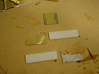
 A quiet afternoon due to rubbish weather allowed me some time pottering with the Johnston A and it was time to start cutting brass. I'm going to build the tops from as much metal as possible to get weight into the model. 3D printing scores huge points for detail and accuracy, but theres just not enough weight in it to be usefull for very small locos.

First was the boiler which was cut to length and then opened up to give the firebox and also to go over the gear tower. I then cut a couple of pieces of brass 6mm by 2mm for the sides of the footplate. The top of the footplate was cut from brass shim with a sharp knife. I then discovered that the way the mech was set up meant that I was going to have to make the footplate part of it. I was also only going to be able to solder one side to the shim and the other would have to be glued in situ.

And heres where we are up to (with the Cb for a size comparison). The boiler is a bit smaller than the photo makes it look. I've also cut out the cab sides after sweating some brass together.


Thursday, September 09, 2021

Precision engineering

 Another post from the being at home collection.

Today I did another small job on the Johnston. The center wheel on the loco needs to be smaller as on the real thing its actually the jackshaft drive.

Now given the complete lack of anything other than a power drill for turning round objets, the wheel assembly was split and chucked up. I then clamped the drill between my knees, squeezed to fire it up and then went carefully with the file.

One side done

Both sides done 

The wheelset was then installed back in the chassis

Should do the job. Unforunately due to the design there was only enough traction tire whels to do one wheelset. on the other hand there were several later Johnston locos which were 0-6-0's ( including a tank loco I think) in case I want to make another one.

Tuesday, August 31, 2021

It lives!!!

 I've been doings some bits on the Johnston loco. The worm gear assembly was attached to the bogie after a bit of filing and some superglue and it all held together (though I'll strengthen it with something harder). Now, those of you who were paying attention and have memories longer than a goldfish will recall I was planning to put the motor in the tender as there's no space in the loco. This was incorect. The connector is a short piece of plastic wire insulation secured with a drop of superglue.

I then touched the wires to a 9V battery while holding the bits together. After a couple of stutters to my suprise it sprang into vibrationy motion. 

So, it goes which makes the rest a bit easier. I now have to build a top maximising the weight, rather similar to the Cb.

Sunday, September 30, 2018

Assembling the bits

So, as with all good bush tram loco builds, we peruse the pages of Japanese N scale spare parts. The key is to identify possible candidates and then eliminate them. Whatever is left winds up in the shopping cart.

So looking at the target.....

We have a 0-4-0 but with the geared drive is actually an 0-6-0. Theres no real space for a motor in the loco so it will have to be in the tender. Now I'm not a fan (that's a bit of an understatement) of tender drive, so that's out. I prefer a motor in the tender driving a shaft through the cab to a worm drive. Pick up on all wheels is a must for any small loco. Oh and we need inside bearings as well (and outside power pickup is surprisingly common).
The big plus is that I don't have a scale plan so theres a bit of flex in my choices and I don't think anyone can tell me I'm wrong.
Well, you could but you would then be told where to go (and its not close by...)
So, after a bit of a hunt we get the following collection.


The "loco" end is from some weird ass Japanese Co-Bo shunter. However its got inside frames which passes the main qualification. A closer look reveals some very small holes which look like being ideal guides for drilling out holes for the crank pins. It also has a traction tire which is fitted for the express purpose of reducing the number of wheel available for electricity pick up, and to make one wheel a different size.
The bogie for the tender could be any one of the multitude offered as spares, so I just picked one that looked like it had inside bearings. The worm drive was picked at random based on the assumption that they are all the same (the gubbins seem to be common regardless of the manufacturer from what I've seen). In this case I was right.
And the wheels are finer scale replacements for Kato steam loco's and limited to 1 per household. I have no idea why, but possibly so that some modeler doesn't corner the market on replacement spoked wheels. I purchased 2 of everything assuming that I would screw something up somewhere along the line.
Motors are mini motors from Nigel Lawton. I've had 2 of these for a long time and it seems to be the ideal project to use them on. Oh and DCC is a given....

Thursday, August 16, 2018

Another journal hunt

Recently I've been doing some more thinking about bush tramways and the locos that ran on them. This time round I'm interested in the December 1986 Journal. From the October 86 journal a list of things to come includes

- A bush tramway track plan, no idea of what but possibly Bob Stotts layout.
- More bush tram modeling
- More bush tram history.

What Im interest in if there are any more loco plans. I have a very basic plan for a Johnston 0-4-0, but I'm wondering if theres anything better out there.


Tuesday, April 29, 2014

In the post

An interesting package today from a shop in Japan.
First up a Bo-Bo chassis. I had been interested to see what the inside of this unit looked like. The bogie wheelbase is 14mm and the distance between the bogie centers is 27.5. Wheel diameter is 5.5mm. No idea what I'll do with it yet, but I'm sure something will present itself.


Next up is a bit more left field. I have been looking at the trams and buses for a while, and when I discovered that you didn't actually need to buy the track sets, I thought 'why not'. Its designed to follow a steel guide wire under the road surface (1-2mm thick from initial tests).


It runs on 2 button batteries and can be stopped and slowed by magnets.
This could be quite interesting on a small layout.
The size doesn't hit home until placed next to the Cb.


I was very surprised when I opened the package.

Wednesday, August 28, 2013

Cruel camera

Sent in By Grant Morell are pictures of my bush locos on his layout. For some odd reason they didn't move and I can only assume ;
1) I need to set up the decoder CV's correctly so that they read DC correctly.
2) The current draw in the Masterton town hall was a bit much to power my DCC box there.

This was a bit of a bugger as I was hoping for some information on how they ran on hills.

 The rail truck precariously perched on a bridge with no pilings. It does look the part from this angle, even if I have to paint the wires.

The Cb on a piece of ballasted track. This view may push me to at least build a small diorama. I've always wondered if stub points can be made to work OK in code 40 rail. Grant has made a pair that work for his layout in larger rail.


Friday, March 16, 2012

In the post

A package I had been waiting for arrived in the post earlier in the week. My bush tram wheels arrived. They are a bit on the large side (2' diameter) but have curved spokes.


Not perfect, but they have to do. I have the brass to knock up some bogie frames so will have to do a jig to make life easier (and less burnt fingers).

Also, progress on the module sides continues, held up by more fishing trips (catch a fish and there is an expectation that you can do it again).


Its coming along well, and I guess I will have to make a decision on the colour it gets painted. I do like black (simple, elegant and frames the layout) but am willing to listen to REASONED argument for another colour, preferably with photographic examples to demonstrate that the proposer isn't on a short list for the loony bin.

Tuesday, December 20, 2011

Short update

Just a quick note on where things are up to.

I've added the canvas cover to the rear deck, and added the pickup wires back into the guide holes. After cleaning out the inside of the syringe tube with a piece of broken fret saw blade it has taken it's first stuttering steps last night, which bodes well for the rest of the build once I get the pickup on the rear axles fixed and some more mass into it.

Monday, December 19, 2011

When the hell did THAT happen?

(In which our hero discovers that he has actually become surprisingly competent at some things without noticing).

When we left our last episode the mech was whirring away happily without getting far, and the cab sides were cut out. Another session at the workbench and things moved well along, without many burnt fingers. I should have taken pictures along the way, but as you are all well aware I just don't roll that way. Suficit to say there was some cutting andsoldering and filing interspersed by the sad little plink of yet another fret saw blade giving up the fight.

'Posed next to my double sized ruler'
The cab actually came together surprisingy easily considering its a collection of odd shapes of metal. The plastic deck at the rear was somewhat simpler to do. Personally I was astounded as it is the first time I've tried to do anything like this in brass, and it all came together well without unsoldering itself once (though it did get quite hot at times). As for the atuall prototype, well its a truck of some sort....
I have removed the pickups for the time being as I have to work out where they will go with the lid on.
'looking better'
Next up the obligatory photo with the Cb for scale. I had thought the cab was going to sit too high to clear the front bogie, but it looks OK. The front bogie has now acquired some bush workshop 'wood' frames to cover up the rest of the bogie bits. There are also the beginnings of some weight in the back. There is plenty of space for more weight in the cab (OK, plenty is a relative term) and also under the canvas top. I must go and find out if you are still allowed to buy lead in this country, of if its been banned by the environmentalists.

Final shot today shows the addition of a dumb buffer (on the off chance that it might have enough grunt to actually move something else under its own power).

Not bad for 5 hours of work over 2 days. Not so good for anything important getting done on the layout....

UPDATE; in response to a question, here is a general idea of how I did it. Basically it was sheer dumb luck.
looking from underneath. The top of the hood is shim brass sheet that is curved over and soldered on each side. I've then put a dashboard piece in that provides the bottom of the windscreen.
The top side. Here's where I got lucky, as I just soldered the brass dashboard in and the solder flowed into the right shape. I think its something to do with the silver content. I'd give you a scientific discussion of this but I'm worried about people falling asleep at keyboards, and waking up with a key imprint on your forehead. It does work though, and I just had to do some cleanup on the ends with a file.

Sunday, December 18, 2011

Distracted

Well, with all the best intentions I ventured out to the man-sion yesterday afternoon to work on Paekakariki (which has now acquired italics to show its importance). Unfortunately I was distracted.....
'The enormous DCC chip is 19mm long'
I have made a few alterations from previous pictures. The rear underframe has been built up from a couple of bits of 0.4mm PCB. The spoked wheel has been replaced by a plain 7mm one though I might replace it with a smaller 6mm one as it doesn't quite look right at the moment. I was pondering how to arrange the power pickup from the front bogie. There is quite a bit of swivel required for the tight curves and I was not happy with soldering a wire onto the pickup as I had done with the Cb. A moment of clarity gave the solution. I have some bits and pieces of syringe needle as it is a good source of small tube. A short piece of this was soldered to the pickup stub, and then a piece of phosphor bronze wire was slipped into the hole (a loose fit) and the other end soldered to the frame. This set up actually works, and the mech has taken its first stuttering steps on the layout. I still have to sort out how to run pickups off the rear wheels without inducing too much friction.

One thing that the test run demonstrated is that it will need as much weight as I can manage to fit in. Talk amongst the peanut gallery had suggested that plasticard should be the medium of choice for the top. However, having a long history with making small locos work in this scale, I picked brass to get some more weight in. I need to get as much weight as possible forward of the rear wheel for traction.

I sweatted 2 pieces of brass together and then glued a paper plan on as a cutting guide. Fret saw and file were employed for the shaping. I've now realised that I may need to buy a second decent file. Also compered with making track where I might go through a fret saw blade every 2 days or so, I've gone through 5 in an afternoon.

Friday, December 16, 2011

Plans

So, after doing all the cutting, it was time to see if things were actually going to fit. Instead of photocopying the plans down, I sometimes prefer to draw things out just to see how things work. It can give you a better idea of how its going to work.

I picked a 1930's ford truck as the base. Well, its actually an Opel Blitz but close enough. I've always liked the shape of this truck and it does fit into the period. The closet bit will be fitting the gear drive under the hood, but I can always jack the front end up a bit. I also looked at removing parts of the bogies but these are not as tightly fixed as the previous types that I have worked on. I'll just have to file all the springing detail off instead.

Oh, and it looks like the decoder will fit under the canvas hood. That is a plus at least.

Hopefully at some point we will return the blog to some more normal subjects.

Wednesday, December 14, 2011

Grasp on sanity slipping?

Over the years I've provided plenty of evidence that I tend to think out of the box a bit, possibly to the point of thinking out of the next box too. I find it very useful in my chosen profession. Anyhoo, a couple of months back I was looking at another bush loco from a Kato B-train.

This wasn't really sitting quite right in my brain,and like most projects that reach this stage in my brain, it doesn't go much further. Fast forward to last week and while looking at photos from a yahoo group I came across something that did send the old grey cell into a bit of activity (and not just the 'rolling over and going back to sleep' kind). A quick search wound me up at the web page of the bush tramway club, and to one of their pages.

OK, so at first glance there are no real similarities, but as I looked a bit harder something clicked. This then progressed to seeing just how much further the Kato underframe could be disassembled. Adding some bits from the spares box (I think it was a Bachmann 4-8-2 trailing bogie) and trimming a bit more and we get.

I still have to modify the front bogie sideframes to something that looks a bit more bush workshop, and sort out the pickups for the rear wheel. Fortunately the front bogie uses the outside pinpoint style pickups. I did have to swap a 1/2 axle that had a traction tire to get more pickups.

So size wise, how does it compare with the previous benchmark (and those who have seen the Cb in the flesh know what I mean).

'Cor boss, that is small!'

The size for the top is 51mm long, and 22mm high. this should just be enough space for a decoder. I may have to remove the motor clip and glue the motor into position.

Must put more thought into a layout at some point as well. They will look a bit out of place on Paekakariki. I'm leaning tiowards something that will fit into a total dimension of 62" (or 158cm) and 23kg total weight, as this will fit on an AirNZ aircraft.

Friday, October 21, 2011

A pattern forming?

Last week I received a couple of boxes of stuff, which I think is a circular thing (take something out, put something in sort of thing).

Among the bits was another little Kato underframe. No use for any real loco but shifting the frame of reference...

OK, so it has possibilities. Whats under the grey plastic hood?

So, the grey plastic clip is just holding the motor down. Out with the fret saw and we get....

The next thing to note is that the PCB pickup holder is no longer held down. just what is it holding down?

Nothing really important. with a bit of work, it has a bit of potential. Possibly as a Heisler, but also another Price's product.


OK so it doesn't have the right bogies, but the side tanks are useful to hide a multiple of sins.