Showing posts with label Fremo120. Show all posts

Thursday, July 24, 2025

Greymouth 1 - a start, and plans for Galactic Domination™

DB thinks:

Despite life and other bruises preventing me from generating massive dollops of progress, a few wee projects have made small steps forward. 

Most interestingly, I'm making some moves on the trek towards Greymouth station now that work on Elmer Lane has slowed down. I'll probably build a steam-era sanding tower there, add some power poles and people, and have yet to decide whether to include a water vat or not, but most of the key bits that I wanted at the depot are more or less done.

So it is high time to start progressing in a northeastererly direction, as has been threatened for some time. This 'planning' (I really need a much looser word here) started in March, and since then, I've been daydreaming about where this might lead. A Greymouth Empire Module Set could easily include:

  • 'a main line connection' to other people's modules (with Omoto bridge and loco dump)
  • The wharf, with its hydraulic cranes serving colliers tied up for loading
  • The wooden Cobden 'S' bridge across the Grey river
  • (and on to Rewanui).
  • (in hindsight, a turnout by the roundhouse could have given a Hokitika branch too!

Greymouth modules concept (not all tracks shown)

It would seem logical to advance this in the following order: 
  1. design the yard throat module, 
  2. at around the same time, link those yard tracks with Elmer lane using 'Greymouth station'
  3. build Omoto to provide a mainline module that can transition to other people's modules
  4. add the wharf for more operational fun
  5. Build the Cobden S bridge, because that would be really cool,
  6. and at the same time, build the Rewanui station/state coal mine terminus.
  7. build at least one Rewanui 'branch' connecting module between the bridge and Rewanui Station to provide a little more branchline running time and interest. The branch/bridge/incline etc wouldn't technically be 'mainline', so could have tighter curves and points than the usual, much steeper grades, and even a (low) centre rail for looks, which could be interesting. I doubt I would make Dunollie Junction (and the Rapahoe Branch) to slot in between the S bridge and the Rewanui branch, but someone else might!
So geographically, the module next to Elmer Lane will be a fairly plain 1.2 metres of straight tracks, but this will house the Greymouth station building (and between one and three turnouts to join the depot into the yard). 

The more 'interesting' module (from a Darryl perspective) is the next one - the yard throat, the tracks across Mawhera quay, the signal box, Riverside station, and the connections to the other future modules. 

The design of this throat should obviously enable trains to come off the 'mainline' and go into the yard/staging tracks (perhaps reversing using the Elmer Lane roundhouse loop first). 

It should allow 'Rewanui to Riverside' passenger or coal trains to operate without interfering with the core layout (the 'mainline'). This includes a runaround at Riverside station so it can be used even if the wharf or Rewanui modules never get built. Freight from Rewanui can be moved straight to the wharf yard, or into the Greymouth Yard. Passenger cars used on Rewanui trains might be stored in the Greymouth Station yard when not in use. 

The wharf should also be operable fairly independently, without upsetting other operators. Its layout should allow trains to come to and from both Rewanui and from the mainline.

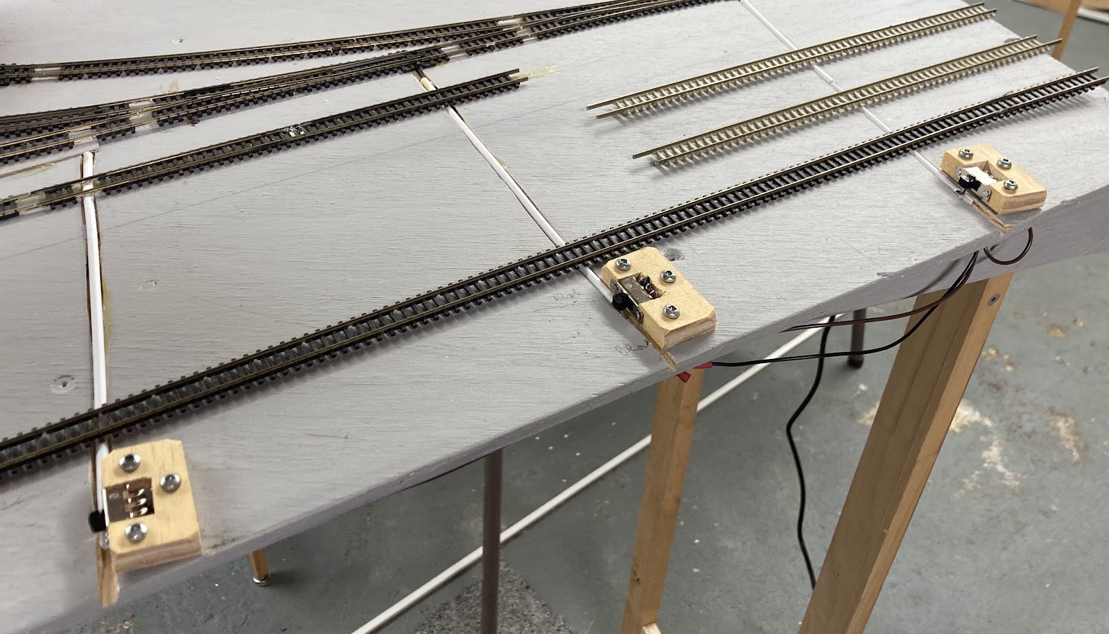
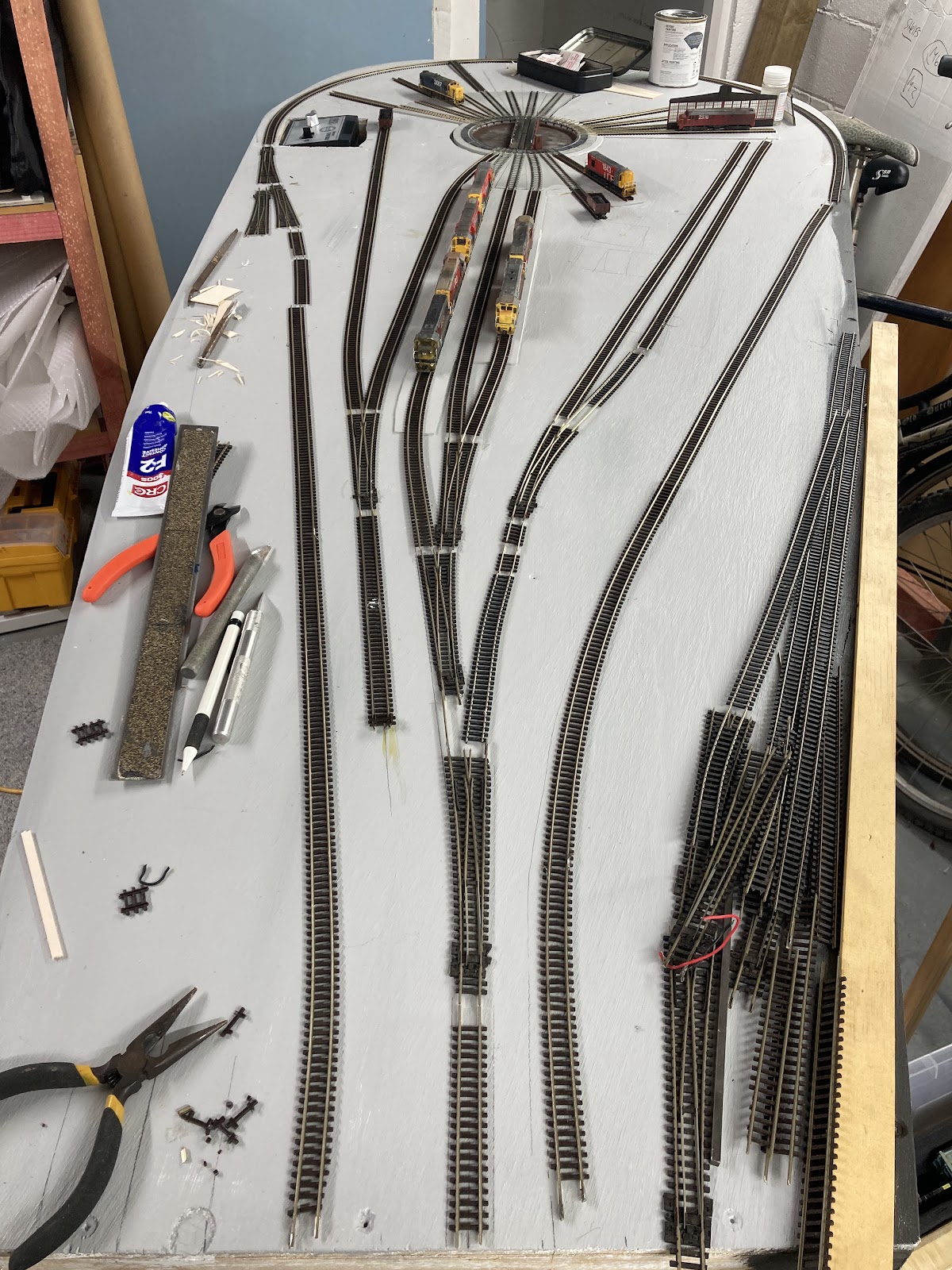
So this is the current thinking, which is fairly fluid, but it hasn't changed too much since it was first laid out in March onto a triangley bit of ply. 


That ply baseboard is an offcut from Elmer Lane, and it has been braced with some bits of secondhand wood that live in the garage.

Monday, March 31, 2025

Fremo

DB notes:

Michael Tolich posted a few pics today from last weekend's Fremo (US HO) meet at Huntly and he has allowed me to post them here.

Pretty impressive for just 15 modellers being present!

They have a big meet each year in Morrinsville that attracts over 100 modules. 


This is what NZ120 should be aiming for...!

Tuesday, January 28, 2025

Elmer Lane 9 - Wired.

DB rolls on, since the miserable summer weather continued on Sunday:

The first thing I remembered to do on Sunday was to cut some channels for my overscale point rodding actuators. This was done with a power saw, believe it or not.  With several cardboard boxes as barriers and some plastic sheeting on top of that (and everywhere else) only a few little patches of sawdust had to be vacuumed up.

I then spent a few hours powerfrogging the three points I needed for Elmer Lane, and did the three I needed for Studholme at the same time.

So with that, the rest of the depot trackwork went in pretty quickly. The curved point at the railcar depot will stay as an unmodified Peco.


I didn't have a lot of spare time on Monday and Tuesday, but did manage to solder (my most hated task) a few dozen wires down to power all the depot tracks other than some the roundhouse fan tracks. 

I also needed to route power to the DCC-froged points with a switch that also moves the points with a wire rod. One of the problems I had with Studholme was getting the alignment right so the switch throws the points. It was easy enough cutting holes in foamboard, but I thought cutting rectangles in plywood without upsetting the screw hole for the switch about 1mm away was asking for trouble. 

So I decided to try mounting them sideways in a thin bit of wood. Cut out slot with razor saw, nail in switch (I did this at an angle for some clever reason I can't remember), cut off section of wood, drill holes for mounting screws (so you don't split the wood).


Solder on the three wires, line everything up, and screw it all down. Use those flat headed screws to minimise chances of splitting the wood.


Reasonably tidy, and at least they are completely functional, and they feel oddly ergonomic.


So two part-days of soldering (the most hated task ever) and its ready for testing tomorrow.

The main/balloon hasn't been tackled, but that should be relatively easy. 

Saturday, January 25, 2025

Elmer Lane 8 - Modulus Completeus

 DB Says:

The roundhouse balloon module inches forward in tiny leaps and massive bounds.

The 'wide legs' were attached and a brace added. No matter how many times I do legs, they never end up the right length. 1100 mm, less feet, less module depth etc. Well these were about an inch too short, so I had to go buy some 'long' hinges to extend them. I figured this would be stronger than sticking bits of wood onto the tops of them, and I'd planned to use hinges anyway. 

Looks silly, but its all quite sturdy. As these 'wide' legs are attached to the underside of the module, they obviously fold up snugly against it. as can be seen in the above pic.

The thin legs at the other end are mounted down the endcap, a little closer to the floor, so they fold up a little further from the module, neatly on top of the wide set of legs. Almost as if that's what was intended.

A little tab attached under the middle of the module (below) can hold a screw to keep everything neat and tidy for travel (except for the brace, which I suppose I could attach under the edge to the right of the pic below).


Finally, some primer and paint was added. Dark grey for the 'public edge' (I had a little left over from the Studholme sides) and 'Harvard Grey' everywhere else, because we had an unopened tin of that with no purpose in its life.

And rather than working or watching the cricket on Friday night, I churned out four more end segments before I run out of enthusiasm. Another 2-4 should do.

On Saturday it was time to bring things inside, which was quite easy, and from there, things went somewhat crazy.

It took me about an hour to fettle the holes for the turntable feeders that I'd 'guessed' the locations for into the right sizes and places, but once that was done, the turntable was popped into place, plugged in, and .... it works! Quite cool really. I didn't try powering any locos, but the spinny thing works well. Coolness.

So then the table was screwed into place and the Kato radial tracks glued down. 

As feared/expected, the 6mm ply pit is a tad shallow, so I started applying some (bass?)wood sheet from Mitre 10 that I happened to have handy and that seems to be the perfect depth. This was painted Harvard grey to match the rest of the baseboardA few holes around the turntable and tracks were filled in using this too, to stop the ballast falling through onto the floor. 

The approach tracks were all glued down into place down to where they will meet the points/turnouts at the pointy end. The track that will likely be unpowered that runs down to the turntable control box was also added (with its point, as its unlikely to be powered anyway). As was the first 'main' radial track outside the roundhouse side wall with DG 2376 sitting on it, and two short radial tracks out by the foreman's office (one with the DI, one with an LA wagon of coal for the office). 

I wasn't planning on putting the track in with the DI, but I thought why rip out the little stub that Kato kindly supplied, might as well put a little track in there. Can always not use it...

So that's some serious progress, next steps will be to permanently lay the main balloon track, and DCC those three points at the pointy end for depot track access. Four if I can be bothered doing the curved point where the two railcar shed tracks split. 

Then wiring, soldering some fishplates up, and testing.

Tuesday, January 21, 2025

Elmer Lane 7 - Baseboards (haha)

 DB rolls on:

A few spare moments had me cutting out my bit of plywood into its balloon loop shape, sanding the edges nicely, and checking it does indeed fit into the car (back seats folded down and passenger seat forward).

Hacked holes for the turntable, the kato fan tracks and the turntable control box were then added (removed?!) with a jigsaw, so these items can be installed with their bases below ground level, which should put the rails just above the surface of the ground where they should be, rather than having the whole depot elevated above ground. If that makes any sense.

Overground holes.

Some reinforcing wood ( I believe that is the term that builders use) was stuck on the back of the module. The whole thing is surprisingly stiff. Surprising for something that I have made. I was careful to not have any 'little beams' underneath the turntable, allowing me to put a solid offcut of ply under the pit and most of the fan track cutouts as a solid base for the turntable. A thin bit of dark brown hardboard will hold the turntable control box largely below layout height and inside the loco crew rooms. 

Undernethers pre-endcap at the small end.

The reinforcing beams have holes drilled in them for the inevitable rats nest of wires. Legs have also been made and attached using little hinges. I'm not sure whether the little hinges, even with upgraded screws, are a good idea or not, but they are quick and neat, and in theory they shouldn't be under too much stress. I'm not expecting people to be mud-wrestling on top of the modules. The whole shebang isn't too heavy, although its becoming a little ungainly for this one person to move with any measure of daintiness.

Other than the plywood sheet, all the wood used for the bracing and legs has all come from a big pile of leftover/recycled/offcut wood bits I have in the garage, so things don't always match in terms of material (and some things are 'that size' because that's a handy length of wood I had to hand), but its not that anyone is going to be grading me on my woodwork now that Mr Birch (Form 1 and 2 at school) has passed on to the great woodshop in the sky.

Completed thin end leg attached to end cap, tidy and sturdy.

Wide legs (all the fashion) for additional stability will go under the turntable end.

I have, as unilaterally declared in a previous entry, made this so the rails will sit 1100mm above the floor, and will take 10cm off the Studholme legs to match. 

Aren't standards wonderful! Everyone should have one!

Monday, January 06, 2025

Elmer Lane 3 - real word curve testing

 DB continues:

So, Elmer Lane, with a more-than-180-degree balloon loop, all able to be squeezed into a car... Well the whole turntable and roundhouse thing wouldn't work very split down the middle across two modules... but is it practical? There's only one way to find out.

Lengths of second hand Peco code 55 flex were unearthed and the soldering iron fired up. It only took one joint at the head of the curve, the other pieces of straight flex were just fishplated in. The curve had four or five staples applied to keep it tight

Then the Digitrax DCC was dug up, it took me a few minutes to remember how it all worked, but soon enough, some of my DCC locos had what might be their first real spin in about 13 years. 

First up was the challenging test train: a light 1990-built LC up front with a glued-stuck Microtrains coupler (connected to a long body-mounted DX coupler that will want to throw out on the curve), some lightweight four wheel and bogie wagons (all with fine flanges), including a KP with a loose weight rolling around inside it, the light and long GT car carrier, my new flat UK and the featherweight laser cut plastic ZH, and then at the back, heavyweights and top heavy wagons - resin castings and the new Trackgang Zs and old CF. This pic taken just before coupling up for the first run.

And... no drama to report at all, except I could only get one of my DXs running at first, so it had to take the train, alone and slowly. Success! 

Then when trying to push it back around, a stall, with the middle of the train in the middle of the curve, and the DX's wheels spinning. But no derailments. I knew this floor wasn't level,  but I didn't realise quite how much. Some books were employed to lift one corner a bit, but to no avail, the mighty DX was beaten on the uphills.

The day was saved by DG 2376, on a heavy Kato PA-1 chassis. Man that thing can haul. Up and down no problems. It was only when packing away the train it was found that my GT has a splayed bogie, so the one wheelset that was left on the track when I picked it up probably wasn't rolling at all. 

After this, it seemed like a good opportunity to play trains. something I don't do enough of.

Here's the single DG on a coallie. The heavy CBs are in the middle (they have pizza cutters which rub on the metal wagon floors), and an even heavier Trackgang CF is at the back of the lightweight CWs. No dramas pulling or pushing uphill at quite decent speeds. This train looked nice behind the two KiwiRail DXs when I got the pair running and multiple-united together, although they run slow.

Not entirely prototypical, maybe the DG should be blue

The TranzAlpine then came out, and this is a pretty heavy train with a high centre of gravity as the cars are solid resin, but they have nice metal wheelsets, so I had no qualms with the DG and later the faster DFT pushing this uphill around the curve at unrealistically high speeds. 

So the verdict is that even my creakiest old wagons in a worst-case consist seem to run fine around this sharpish curve. And so they should really, this is flextrack laid out in a smooth, flat circle with a single soldered join, and an 18 inch/450mm radius curve isn't crazy tight. With a more sensibly-ordered train (heavies at the front, free-rollers at the back), I can't see this curve being a problem unless there is way too much speed and herky jerky operator error.

More worrying was that many of my locos didn't work, or took a while to get working, or barely worked at all.

A few may have an incorrect address programmed on the decoder for some reason, such as DG 2330 and DJ 3067, both of which were DCC-ised not long before all this stuff was packed away. I didn't think to get out a programming track to see.

None of the Atlas SD35 chassis under the Da/DBR/DCs worked well. Cleaning and better electrical connections between the decoder and metal split frames are required, although I did have DC 4559 and 7132 (both blue) on the Tranz for a while. 

DF 6277 and DX 5448 ran jerkily, and DF 6064 could barely turn its motor with lots of humming, so something must be binding in there. These are all old Kato chassis with decoders that were hardwired in 1995 for my little 'Wellington' layout, built after I purchased the Digitrax. Amazing to have an electronic anything that still works after 30 years and will even drive modern decoders.

The two KiwiRail DXs on Atlas Dash 8 chassis with clip-in decoders are nice and smooth, but must have their VMax set quite low, perhaps to run with slower locos? Their maximum speed at 100% is preeeetty slow. That should be fixable easily.  

The stars of the show were undoubtedly DFT 7132 and DG 2376. And the curve. 

.....

However, I don't want to get too distracted by this until I have finished the hard work of Studholme...

Sunday, January 05, 2025

Elmer Lane 2 - Meanwhile, back in the real world.

 DB continues:

With the arrival of a thin 8x4 plywood sheet on the second of January, it was time for a more realistic think about Elmer Lane. To start, the balloon loop curve was marked out at an 18 inch radius. This is smaller than intended, and smaller than the 600mm specified in the Fremo120 doc, but certainly larger than we have gotten away with in the past.  This wouldn't work being 'split through the turntable' into two modules, so one has to remain moveable, and a 4x8 module is completely impractical for transport, housing, flexing and so many more reasons! But that's one heck of a curve. The Trackgang minimum radius is 600, the same as the standard, and they probably don't have many 180+ degree horseshoe curves. Hmmm. This could be a big mistake in the making.


This setup looked pretty decent though and ended up at just over 7 feet long. While I don't intend to move this in a medium sized non-hatchback sedan car, out of curiosity, I took the measuring tape out to the garage. Crikey, the car would actually take 7 feet from the boot through to the back of the passenger seat (seat far forward and with the seat back vertical). The tightest distance between the carpet on the car's wheel wells is three feet. Wow, so with a little shrinkage, this module could fit in a car if it had to! 

Considering these new self-imposed constraints, as can be seen in these three pics  I moved the loop curve a little closer to the roundhouse, which means I'd lose its workshops extension out the back (or it would have to be minimal). The yard throat end lost about two centimetres with no drama. I reduced the baseboard width to 18 inches at the curve end, and thus obviously the curve radius even more, to about 17.5 inches, or just under 450mm.  The track will be quite close to the baseboard edge at the two widest points, but the baseboard can be out further almost everywhere else. Those two spots could have little fences for peace of mind. 

As can be seen, there is enough space for the two track railcar shed parallel to the Hoki line, the rails of which were extended almost to the roundhouse. 

I also have the track (near the turntable controller box here) which served coal (that white solid resin LC top at the end of the track!) to the shed boiler, plus a backshunt at the other end. I'm thinking all or some of this track might not be powered, but just a place to park locos for show. Some (maybe many) of the roundhouse tracks might not be powered either, depending on how easy or hard that is to do. Not as hard as I feared it seems. 

I remember in past exhibitions we often took off locos to give them a rest, or because they failed or became unreliable, or needed a wheel clean, just to change things up and it was handy to have somewhere handy where they can still be showed off. And be a place for non-DCC or non-working locos to safely sit and be seen. In the past this was the Otaki goods shed or ballast pit! A loco depot is a better setting!

You might also notice four tracks out the back/return of the balloon, which will be visible staging and train storage, ending up at Greymouth station which will be the 'next module'.

As this will be a balloon loop when it connects back up at the top, track polarity will be an issue, so presumably a DCC auto-reversing section (I know little about these) in the curve would make operation seamless, and ideally the loco depot itself would be on its own power district/booster so that any problems, derailments, or mistakes causing shorts wouldn't upset the mainline operations.  

Hmmm. Intriguing. 

Saturday, January 04, 2025

Are you mad? Elmer Lane 1 - Genesis

DB says:

When the idea of Fremo120 was floated, operational practicalities at a public exhibition would mean you either need to: 

  1. Assemble a loopty-loop layout. This is easier to operate, but challenging given the freeform nature and sizes of the modules. Its not impossible with advance planning and some on-the-day bespoke construction of a basic-plain-join-module using a lump of wood, a saw, and some flex track. Rhys and I did this at our first Dynamic Duo NZ120 exhibition appearance, which used temporary flex laid on a 2x2 piece of MDF (for the end horseshoe curve) and a long stick of 4x2 for the track behind my Otago Central bit. A few screws and a staple gun, and Bob was our Uncle.
  2. Have balloon loops at the terminus of each 'end' or 'branch' that you don't want to have to 'run around' trains at and take them out backwards (most of my wagons are different weights anyway so I'm not sure whether my coal train would run too well reversed). While these balloons are an operational necessity on layouts, the ones I've seen at exhibitions have always seemed a bit 'forced' as balloon loops are not common in the real world, and thus are obviously a challenge to scenic. 
So a couple of balloons probably need to be made for a Fremo120 exhibition layout. But what to put in the middle of one? 

While perusing the Kato Swiss RhB offerings on the website of my Japanese purveyor of such addictive substances, I saw that Kato make a clever little motorised turntable (I had no idea). A lightbulb went off. What about modelling the Elmer Lane turntable and roundhouse? With the 'mainline' to Hokitika running right in front (just like the real thing) circling around the roundhouse (not at all like the real thing! But potentially hideable with trees, or a highway overpass, or something.)  And then the track comes back around the back of the depot where the old workshops / yard is. 

Elmer Lane loco depot in 1969 just after the end of steam (Retrolens)

Elmer Lane loco depot  in 1988 after the roundhouse was surgically reduced in the 1970s. (Retrolens) 

Fortunately, the pricey Kato turntable was out of stock, but upon my next order, it wasn't, and one fell into my shopping cart. This was about nine months ago now, as there have been plenty of other things to worry about in the interim. 

During those months, a bit of pseudo-planning occurred in Photoshop. Of course this is very guesstimental, because in the real world, tracks and things are very different sizes and geometries than when drawn on paper, PowerPoint, Photoshop, or even the track planing software I've tried, all of which are coated in a sheen of optimism as to how much can fit in a given space. But here you go (my doodle used the Kato diagram, overlaid with the retrolens aerial pic, and with some tracks drawn over that) :

(Flipped to make it easier to compare to the prototype aerials above)

Here is the the Kato turntable by the way:

Unlike many N scale turntable offerings, it does have a shallow pit (yay), however the bridge girders are 'upside down' compared to NZ turntables (boo), but surely the sides can be flipped to look a little better? Its modelled on an electric one with a gantry in the middle, but I'm sure that can be removed, and there is a little red operators cabin at one end. The bridge length is a smidge short, as we are 1:120 and Japan is usually 1:150 rather than the usual N 1:160, but its not actually a million miles out. In fact according to my calculations it should fit a scaled down Ja wheelbase. The tracks are radially spaced a little bit wider than Elmer Lane, so there will have to be fewer stalls than the prototype's 18. I reckon about 15 or 16 might be doable to keep the same shape as our roundhouse. 

The really nice thing about it, is that it indexes and locks to the tracks, and has some power routing capabilities too. 

As for Elmer Lane's roundhouse, one of two 'proper' ones that NZ had (three if you count the little three track Lyttelton one), the prototype will house the length of an Ab inside, and that should be doable in NZ120. The workshop extension tracks housed another Ab in length (and even longer than that on one track which had a wheelset drop table, and one assumes from the aerial pic that length was added to each of the three tracks (presumably to house J/Ja locos), but I won't have that much room available.

Thursday, January 02, 2025

New Year Modelling Day: Waihao Forks Update

The Southern MD contingent got together on 1 Jan 2025. What better way to start the year. 

A quorum was quickly declared with three attendees. 

All the tools, none of the skills.

The first item on the agenda was looking at stuff, chatting and pondering.

The second, and primary item, involved bringing the Waihao Forks module out into the sun for the first time in a few years. Its a really impressive wee piece, with a lovely CNC cut ovoid shape, hand laid code 40 track that was completed by Trackmaster RB about 15 years ago and wired and adjusted by MG around 2016. Time and relocations had resulted in some damage to the ends, so it was decided to add Fremo120 ends for connectivity and protection, 30cm across. 

Damaged code 40 track sections at the ends were replaced with Peco code 55, which looks a little Cold War in comparison to the filigree handlaid stuff, but we needed to extend the tracks out over the new endpieces, didn't have any spare code 40 handy, nor anyone who could deftly work a soldering iron to the standard required. 

This worked out OK. Peco code 55 is of course the same height as code 80 but with two track webs - one visible, and one buried in the sleepers, which is why the stuff is pretty sturdy.

This pic from a precious MD post on track. For the transition to code 40,  bottom web of the Peco track was filed off, leaving a much finer piece of track with a web on the bottom. A fishplate was added to this remaining web, and the top of the rails filed down a smidge to match the height of the code 40.


Some of the sleepers were removed and replaced with a thin PCB one to help with the height change. Sounds a bit dodgy, but wagons rolled very smoothly through this. It will all be ballasted over to hide the worst of the chunky bits.

The ends were soldered down to EB's ModelTech rail aligners (copper clad PCB sleeper module joiners with little notches to facilitate alignment).


The meeting adjourned for a late lunch at a nearby hostelry. 

After sustenance had been taken, work continued on the end pieces, and on freeing up and repairing two turnouts. This required freeing up the rodding and reattaching point blades to the throwbars. One was successfully resuscitated, and one remains a work in progress.

Among a few other projects tackled, MH brought along  "The Grassinator" so we all had our first attempts at static grassing a small test section of DB's Studholme. The first task required was to perform surgery on a donor power adaptor to get the right voltage and polarity into the beast. Our results were mixed, being three men who just decided to crack into it rather than reading the instructions first. This is a topic that we will revisit in a future post. Once we have read the instructions. 

But a success for The Forks, which is looking rather nice. 


Sorry to the purists, but we had no ye olde period rolling stock on hand. 

Saturday, December 28, 2024

Elevation, and more wagon rejuvenation

DB continues to rehabilitate dozen-year old wagons:

With the dramas of Christmas now behind us, it was time to pull out some more damaged wagons. Most of these have moved country a few times and despite being fairly well packed, a few bits have fallen off, quite a few couplers have been damaged, the odd bogie is broken, and even a dozen years ago there were a few cripples amongst the herd.

A bit of gluing and cannibalisation had four of the 40-footers back in action, as well as the four HLC coal carrying wagons. One of these has been a chronically bent UK for a dozen or more years. It was replaced with a straight UK borrowed from under a 40 foot container which I have other plans for.

The HLC set is below (on three PKs and one UK), with the bent and disgraced UK (now sans containers, couplers and bogies) lying on its back:

I could probably do another one or two additional wagons with HLCs as I have a few spare bits. A few of the worst wagons (including that PK with four green 10-footers, and some of the other sticky container castings) are being binned. 

Some "1990s-era" wagons are in the track behind, including the roadrailer, which is still on some ancient Bachmann(?) bogies with old school rapido couplers. The roadrailer, the IB with 3x20-footers, and the Spaceracer were built in the Otaki-to-Cass days. 


A few of these locos were converted for my West Coast fetish of a decade or so ago. Wish I'd left the zinc etched blue DXC in Fruit salad now. Maybe I'll strip the paint off and repaint it one day.
I've also been thinking about the Fremo layout height. I absolutely love the 1200mm above the floor height personally, but it might just be too tall (with a backdrop) for most people to reach over comfortably at exhibitions. Maybe for me too. 1200mm might be fun for playing trains, but it isn't very exhibition-friendly when punters are forced to observe from a distance, and as I'd like to join up with the Trackgang layout one day, with its rail height at a more exhibition-standard 1000mm, that would require a massive gradient to bridge 20cm in height... then consider the heavy resin and whitemetal wagons.  Perhaps the incumbent should set the standards... 

Maybe I'll whack 10cm off the legs and see if that is a reasonable compromise. Even down at 1000mm (a bit low for my liking personally), I could always sit it on simple riser feet (or even bricks) at home for my own use.   

Tuesday, December 10, 2024

Studholme 11 - more trackwork

 DB says:

'The schedule' allowed a few hours back on the Studholme modules today. 

It has now been more than a year since I started this, further cementing the blog's status as holder of the Guinness record for longest-average-elapsed-time module builds (thanks also to Paekakariki and Waihao Forks). Clearly long gone are those youthful days of blitzkrieging up a module in a week.

Its been a warm 10 days down here on The Mainland, and a kink revealed itself upon my arrival. Half a mm of rail was taken out of that track and the thing reconnected. All the other tracks seem fine, as a little space was allowed for this in the rail joints.

Some manual point controls have been added to the points on the Waimate Branch (backdrop) side of the layout. 

The three 'mainline' points at either end of the module set will be the most used, so are being made DCC friendly (whatever that means) and each is controlled by a slide switch discretely mounted at the side of the layout, via piano wire.

The four other points on the branch side are 'as-is' Peco points, controlled by more of this chunky piano wire and covered with some oversized tubing in a most agricultural fashion. speaking of agricultural, I see the code 55 Waimate Junction Y here still has some code 80 tails soldered onto it from its last use! They remain in place as the only code 80 on the modules!!

The three points on the other side (east side with access to the goods shed and fruit siding) are as-is with no remote control at this stage. I doubt they'll be used much, but if they are, I suppose I could work them with some actuating wire under the module.

So track has today been fixed down right up to the three south end mainline points, which I still need to make DCC-friendly. The coal/seed siding was also spaced further out as it looked a little close to the others. Darryl P suggested extending the coal/seed siding to serve stockyards there, which might be feasible. I certainly want to have the Studholme Hotel modelled as a flat, and the stockyards should/could be to the south of this, and a good way of fitting something small into the thin gap between the branch's curved point and the backdrop. We shall see.

The 2010s-era 17-wagon coal train was laid out on the loop to check sizing. As predicted, the loop is about 10cm short, so I'll have to drop a wagon if I want the train completely ensconced, although a train this length would be fine in reality, as it's in and clear clear of the mainline for crossings, and an oncoming shorter train can safely run into the siding (closer to the camera in the pic above), although some shuffling of the coalie for-and-aft might be required to let the shorter train out. In hindsight I should have positioned the mainline points out closer to the ends of the module set, but its a bit hard to move them now.