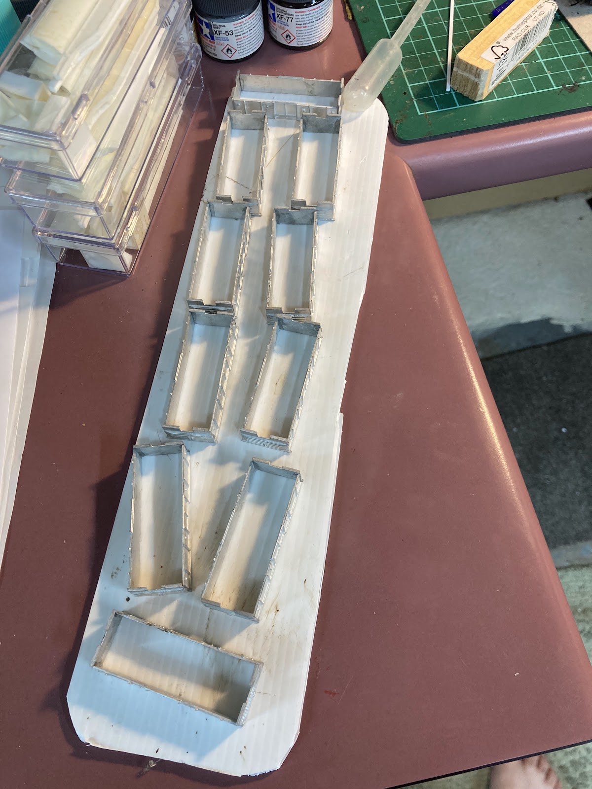
Wednesday, April 17, 2024

Let there be light

At the request of Mr Bond, tonight I'm having a chat about my foray into layout lighting.

One of the (many) positive things about having a play in diffenrent (and commercial) scale is that you get to have a crack at quite different things than you normally would ie the "nice to have" rather than the "need to have".

The positioning of my On30 layout was such that in the afternoons the sun shone from behind the layout and even the lone light in the room could not compete (oh, did I say there was only one light...)

A bit miserable at the back

The real problem is the inconsistance of light across the layout. So you need a lighting system and more importantly something to hang it off. And this perplexed me for a while. 

The answer (like the question) comes in 2 parts.

For the lighting system I went with commonly avaliable LED strip lights (5m with adhesive backing). There's a huge variety but I picked the simple-est (and the cheapest at just $10).

Hook it up to a 12V supply and you are away (in this case another power supply from the home electronic graveyard, which is also running the ambient sound).

The answer for the second part came out of a trip to Mitre 10. They (and Bunnings, but Mitre 10 is closer) stock a selection of aluminium shapes in various lengths. Now a key thing for a lighting setup is that it doesn't blind the operators. As my On30 layout is against the wall I decided that I could use an angled shape to avoid blinding my operators.

So, setting it up, how does it the first iteration look? The LED roll was stuck to the vertical face of the aluminiun angle.

Lighting, tick, more importantly no blinding light shining back. The supports are 2.4m apart. But with the main light out..

Its nowhere near ideal at the front of the layout as the direction is straight out from the support. So I ordered a second 5m roll. Meanwhile I started to ponder the necessity of having a middle support as there is not much weight in the aluminium angle. 4 pop rivets later....

Its unsupported over 4m and seems to be quite happy with this. And with a send LED strip added to the horizontal face we get a vast improvement in the lighting (without the room light)

 I'm very happy with the way its turned out. Its nice to be able to work on the layout with decent light and the support is very unobtrusive. 

The LED strip itself is also quite flexible.

The striop can be cut up into 3 LED sets which have their own resistor to run off 12V and can be soldered on the copper pads so there are a stack of potential uses.

Now, for lighting a freemo setup I would look at using a U shaped channel suspended down the middle of the module with an LED strip at the bottom of the channel. You might need to use a spacer to improve the light angle.

Monday, April 15, 2024

Venting - TrackGang Ventilated Z van - 3 - wheels and weathering

 DB Says: Step away from the paintbrush.

So the 'wheels and couplers' dilemma resolved itself fairly quickly. The one set of assembled Trackgang 'old style/passenger' bogies supplied, were indeed used on Z roadsiders on the old Limited expresses, but this is before my timeframe. I might save them for a future 50 foot passenger car. The kit had an ideal style of bogie for my era, but the frame has been assembled way too wide, so the wheels won't sit in there (bottom-right below). I might need to find someone who has low-temp soldering apparatus that can thin it down.

In the meantime, I borrowed the set of Arnold/Rapido coupler-equipped GraFar bogies that I own (stolen off a slightly bent UK wagon) and used these on one wagon, as the couplers have almost-long-enough reach. 

On the other wagon, I stole a spring loaded Arnold/Rapido coupler from one of my horrible 1991-cast Lc highsiders and body mounted it, sticking it out a little so it can couple to the other Z with its short-reach couplers. With the spring it should be OK on curves. At the other end I attached a body-mounted MicroTrains, which will couple to the locos. The bogies on this one were from Kato Japanese tankcars, and stolen off another old NZ120 wagon - this place is starting to look like South Auckland with all these wagons up on blocks...

Some truss rods were attached - bent brass ones on the side and plastic rod in the middle. I should complete the angled parts of the middle ones, but I'm not sure they can be easily seen...

As for a final review of the Trackgang kits, I'd say four out of five. If it had a 3d printed roof and pre-assembled bogies it would easily score ten out of five. If you see any of these floating around TradeMe, snap them up.

But then some bad things happened. I've been accused of over-weathering things before. And with good reason:

I did somewhat go to town here. Usually my weathering strategy is: eeeeaaaasy does it...  oh, that's a bit strong, I'll go back and.... Oooo, now it's worse. 

Urrk. Ugly closeups. And the other sides:

Bonus:

I found my old XC master from ten or so years ago in a box of goodies and thought I might as well turn it into a third XC wagon.

A use for some Trackgang bits I didn't use from the Z kits is seen below, as the plasticard top is super light:

The finished wagon is top-right on the ventilated wagons 'family pictures' above. 

Venting - TrackGang Ventilated Z van - 2 - painting

DB was pondering with Mr Bätchelé de yong the other day: 

We came to the conclusion that the main obstacle of modelling progress is inertia: the tendency of objects at rest to stay at rest. The (positive) converse being that objects in motion tend to stay in motion.

I have a fear of soldering, and a fear of spray painting, among many other fears, so my Z class wagons have been stalled for more time than they have been moving forward. Yet after almost a week of over-thinking and worrying, I managed to prime the metal bodies with a can of Tamiya Surface Primer. Something I've never used before.

And by golly it's good. As this stuff contains chemicals known to cause cancer in the State of California (which is probably not what they mean, and besides, they even put this warning on cornflakes over there), I took it out into the garden and applied four or five very light coats instead of the usual one big lumpy one, which is always my default mode when spraying (cover, damn you, cover!). 

With the light sprays, the wagon bodies slowly turned grey and more importantly, all the detail was still visible and with no paint runs. Go me!

The stalks here were bits of dowel from the dollar shop used for Z scale bridge pylons the day before and the leftovers and offcuts were stuffed into a box. My, I think I'll save this Mighty Wagon Holding Apparatus for future sprayings.

Despite the natural desire for my moving objects to stay in motion, I allowed the primer a day to set and then put some white on the sides. This was a mix of some sort of Tamiya pure white acrylic, tinged with some grey/brown and some yellow/brown. This all came out a bit grey and dark for me so I applied (a lot) more white to the mix and overpainted. This was all done in vertical streaks to imbue a mild form of 'weathering' into the base, as the Zs that I saw were never ever white.

As an aside, I graduated from Humbrol enamels to Tamiya (and other) acrylics about 15 years ago. I liked how they set so quickly and could be thinned and cleaned up with relatively non-smelly water, isopropyl alcohol or thinner. They also seem to last longer without drying up in the tin. 

The one downside being that they have a very short working time, so if you're taking your time, they can start to blob up and peel off. A few years ago I discovered 'Tamiya Paint Retarder' and this is magic stuff, with a drop added to your mix giving you far more time to work. Yet it still sets quickly so you can still move onwards, ever in motion. My mixing trays are usually clear plastic covers from glue and the like (to the left here, with various shades of white to pick from)

As I wasn't sure where the roof join paint line would be, I overlapped the side colour onto the roof. This additional layer also helped fill any gaps between badly glued together parts. You might be able to make out some slightly different shades from the different layers. There is more brown in the ventilation grilles for example.

Then the roof was painted. I always remember this as a yellowy brown colour, but looking at the Cousins Brothers (Cuzzie Bro's) Pictorial Railways of New Zealand, it seems this was more of a chocolatey brown, so away I went. 

I was very careful doing the join with the white, and very uncareful around the roof ventilators, where a few holes needed to be blobbed up with paint. 

As a first step in weathering, I also added some Tamiya Panel Line Accent wash to the louvres (you can see this on the rearward wagon. More on weathering later, but for now, this thing needs trusses added underneath, and then decisions will need to be made on bogies and couplers. 

These will be in the '80s' train, and for ease of wagon mixing, this train will have the old style rapido couplers throughout (95% of my '80s' wagons do already). As these are the heaviest wagons I have, they will track nicely behind the locos, which have body-mounted Microtrains couplers.

I mentioned this earlier, but this is probably the nicest piece of NZ120 that you can't buy right now (as they don't seem available anymore from Trackgang). The sideframe detail just below the white body is great (see the first pic on the previous Z post), and the bodyside details sublime. Wrangling and fitting the roof was a pain, and I made my drilling mistakes with the roof vents (again, a one piece 3d printed roof would do wonders here). But these really are top shelf so far. 

Saturday, April 13, 2024

The other side of the fence

 Over the last couple of months (as you will have noticed) I have not been doing a lot of modeling. Now normally this time of the year is a low modeling productivity time as we are all expected to do things outside, or at least be somewhere visible to the rest of our friends and family. But I currently have other distractions. 

Before you all say "oh no he's gone mad and headed off to another scale" Thats not quite the whole truth. I I  started off buying On30 stuff 15 years ago as it was cheap and reminded me of 19th centuy Baldwin equipment. I even built a layout after we brought a house and I had no space for Paekakariki. I nearly sold it last year. However it has proved very usefull to properly test a new cheap DCC system. And while doing this I have had an epiphany of sorts. 

NZR modelers are model makers. Its simply who we are and where we have come from, given that there is no RTR. That means assembling a sizable number of locomotives and rolling stock takes a lot of modeling time. Then on top of that there's building a layout to run it on which really isn't trivial either, both in terms of work and time (though hand laying your own track is never going to set any records).

I'll contrast this with US modelers. Now I will be the first to admit that I have less interest in US railways than I do in the tax codes of Bohemia in the 15th century (though the armies are another matter entirely). However one thing that they do do extremely well is building layouts that operate like the real thing, quite unlike anything else on the planet. And I think its something NZR modelers really miss out on. 

I think that the big issue is that for most of the stations in New zealand between the main centers, theres not much difference in design. "n" Passing loops where "n" is a number betwen 1 and 6, a goods shed on the  furtherest passing loop from the station building, if n is >4 an option for an engine shed and/or possibly a way and works yard at an end. Oh, sorry, and options for either being straight or on a curve. if there4 is an industry its something to do with agriculture. You really have to go out of your way to find something outside these options (ports being an obvious exception). Whats really missing is the "play value" and by this I mean not just letting trains run, but stopping to do some shunting along the way. For this you need rolling stock that runs well, track thats layed flat and a coupler other than the standard NZR( if you want to go "hands free").

 Junctions are a bit more interesting but you start to hit size issues in the larger scales (as with the larger "n" stations) not just with length but with width as well.

Right, I'm going to post this now as I've been adding to this for a month and I should draw a line and throw it out to the peanut gallery for comment.

Tuesday, April 09, 2024

Venting - TrackGang Ventilated Z van.

DB says.

Just looking behind the curtain at the blog now, there seem to be half a dozen little partially-finished posts of works in progress. I've also been distracted by life, and models in 5 separate scales, but many of those half-finished bits are mine. And I swore I'd never become a rubber-gauger...

So in the face of that, why not start another post on something completely different.  

I've always loved Z ventilated vans. These were the long 50 foot white 3-door wooden ones with louvres, rather than the non-ventilated ones that were usually red oxide, or in the 70s/80s sporting various colours carrying parcels on our passenger trains).

They were quite popular at Studholme in the old days I'm told, carrying strawberries and other produce away. I recently read in a book of local history that they were usually marshalled next to the van at the back, so the guard could enjoy the smells!

Imagine my thrill when a pair of Trackgang examples came up on Trademe. 

Now, if you've been reading MD for more than 10 years, I know what you're thinking, as I've had pretty mixed opinions of Pat Eade's old Trackside kits, but I came into this with an open mind, but with a bar that was set fairly low way back then.

First impressions: Wow. the castings are impressive. Incredibly well detailed, clean, crisp straight lines, thin walled to keep the weight down. - far better than anything I've seen in NZ120 with the exception of the laser cut Batchelor Sheep Wagons. Certainly far more impressive than 3d printing seems capable of at the moment (there's a challenge thrown down!) 

As for the bogies, one set was assembled (bonus! as these have always been a pain for me to do). They have pinpoint bearings! More on the bogies later when we get to them, but for now, let's start making things. 

A quick whiz with a file cleaned up a few of the edges on the sides and ends, and things were straightened out and flattened after being in a mailing bag. But there was actually almost no flash to speak of. Just in case I wasn't clear, these are some really impressive parts in my fingers.

The only fiddling I did was to remove the coupler pockets with a Dremel drum, as I'll probably fit either MicroTrains or old Rapido ones. TBD.

You may remember from many earlier postings that I can't solder my way out of a balloon, so these were assembled with some random brand of super glue gel and strengthened with Araldite epoxy. 

I've never used gel super glue before, and it was certainly more forgiving than the usual stuff, but the faster acting stuff is probably better, as just when you think you have this sorted it collapses in a heap as the glue hasn't decided to set yet. Problem solved with a few tins of paint to keep things more or less square. Look at the detail. Superb.

Oddly, I read the instructions, before doing the opposite. I stuck an end onto a side, then put in the floor, then the other end and side. And I'm glad I did it this way, because the roof required quite a lot of thinning to fit in the supplied recesses.

Then it was time for the secret weapon to add some glue fillets inside to bolster the superglue:

Here is the roof going on. It required a fair bit of fling and bending to get it flat (well, "flat" to match the "almost-flat" metal box I had made). I drilled out the vent holes as suggested, but used a drill bit that was a little big. Which is silly, because I have the right sized one on my bench.  
The vents come three to a sprue (right side here of the pic below, seen both attached to the sprue and clipped off) and the little tails poke through the holes. Clever enough. Arguably the roof-plus-vents would be a nice 3d printed addition here to eliminate this relatively fiddly step. My clumsy fingers and failing eyesight proved the super glue gel's claim that your fingers wouldn't be instantly stuck to things to be only partially correct. Not instantly...  A 3d printed piece would also reduce overall weight and move the centre of gravity lower. I did consider using some bent plasticard, but that would have left me with one nice edge, one terribly rough fettled one, and vents all over the place.

More to come. 

Wednesday, January 24, 2024

Light at the end of the tunnel.

 Last night at 10 pm, No 1's front headlight sparked into life and the new DCC system went live.

Like anything electronic here at La Casa Dandruff, things fought all the way to the end. When we left our story last time, I was cursing the creators of Ubuntu to a short walk off a very high plank. This also forced me back into the arms of the devil ie Windows....

Creating the Windows 10 boot USB gave problems with the file size which required the third suggested solution of those I tried (after the first 2). The install itself went fine, as did installing Java and JMRI. The computer picked up the DCC-Ex and I could then set it up under JMRI.

I purchased my Arduino and motor shield with DCC-Ex pre loaded for $65 from JT electronics in Hawks bay. They also do quite a few other electronic dodads.

The final install started with me having to get wires into the small tag board, and doing some trimming as I had folded the wires over to make them stronger which didn't fit. I then got no life from the track (including trying to induce a short). Worried that I had "bricked" the Arduino I dragged everything back into the living room to download the DCC-Ex program to see if it would read. Firing up JMRI, I then discovered that I had not turned the track power on in JMRI.

Back to the train room, plug it all back in and again no life from the power pack. However I noticed all the other lights on the outputs were lit. I then swaped the powerpack for a 30 year one from a Mac aquired back when I worked at Victoria university (which has also been the power supply for the Paekakariki loco depot). Firing up old reliable and pushing the light button for the front light on No 3 and theres life.......

The sign of success


 At this point I had a play for 10 minutes... And that will waste soo much time in the future.

To finsh this section (since its not an On30 blog) does anyone have any questions on the DCC-Ex setup? Its a bit complex online but in real life its very simple.

Saturday, January 20, 2024

A cautionary tale.

 In past days when the earth was younger groups of humns roamed the globe. And when they met they would swap stories late at night round a fire pit of horrors they had seen...

Last post we had an introduction to the DCC-Ex system. This runs on an Atduino mini computer with another module (called a motor shield) to power the track. The unit itself is quite small and both bits can be had very cheaply from Aliexpress.

The computer (the DCC brains of the outfit is underneath, and the module on top is the motor shield with the connections to the real world at the top right. 

So, next up was the connection to the throttles and ther stuff, a Laptop running the JMRI solftware. This is a free, powerful program which lets you control almost everyting on your DCC layout, from tinnkering with decoders right through to controling the layout. So out I dug a 15 year old laptop from the old elctronics collection that every household now has. It fired up and while it ran a bit hot and a bit slow, I figured that if I got rid of windows and ran a freeware Linux system It would be fine.

If you don't understand some of the terms in the following story, do not worry its perfectly normal and you can just switch off till the end.

The lunix system I shose is called Lubuntu. It is a stripped out version of Ubuntu (a well known open source version of Linux) for use on older low spec laptops. To install it you first need to download a file for the operating system and then creaty a boot USB stick to transfer it onto the target laptop. all good at this point, and I fired up the laptop. The operating system was installed overwriting the previous windows system (there is an option to run it as a trial to see if you like it but I didn't need that). I then needed to download some updates. Hmm, why is connecting to the WiFi blanked out? A 10 minute hunt reveals I need to conect my phone and turn it into a hotspot. Right, the update loads and the laptop now conncest to the WiFi. 

Next, I need to have Java to run JMRI. What version do I have loaded? Hmmm, none...15 minutes sorting how to do this and getting it sorted. Then download JMRI and extract it to install it. Hmm, how the hell do I fire it up, there doesn't seem to have an icons on the desktop. Maybe I've installed it wrong. delette and try again. Repeat 3 times. Re-read the documentation and discover I have to create my own launcher icons (WTF). Then theres configuring the USB ports. And I can't set up JMRI with DCC-Ex unless i know which port is which...

Talking to Drew today, doing this under Windows is a piece of cake. Everything just goes from A to B to C and it just works. Bastard.

So the end of the story is this.

Don't try this in Linux.

You have been warned...

Wednesday, January 17, 2024

DIY DCC

For the last couple of months locally there has been some experimentation with a DIY DCC setup, DCC-Ex. This is an open source project based on the Arduino minicomputer and add-on's. 

At this point I should introduce the beast. The computer box on the right contains the Arduino with DDC-Ex loaded and a motor shiled for the track power. All this is powered by a computer powerpack. The Arduino is connected with a USB cable to the laptop running JMRI. In the first iteration, the laptop is connected into the house WiFi network. 

 The throttles are smartphones running the Engine driver app, free to download which can run 2 locos per handset at once.

The speed is controlled by a slider on each side of the screen. At first I was skeptical about it, being a knob man myself, but I now quite like it. 

The test animal is an On30 layout that I've been working on slowly for nearly 10 years. A few months back I tried to sell it, but there was a lack of interest. It was all rather fortunate as this became the test bed for the DCC-Ex setup.

Drew brought the setup round one afternoon and it was on to the show. We spent the afternoon just getting used to running trains using the system. There were a couple of WiFi dropouts due to the positioning of the laptop, this was solved when the laptop was moved 3 feet closer to the home WiFi router.I took some photos but Drew is quite shy so theres just some layout shots

Number 1 and Number 2 on shed waiting for the next turn.

Number 3 about to depart with a surburban service

Number 6 moves off to the port (still to be built).

 
After the first session revealed a few inprovements that need to be made, mostly to get the track more level and a few out of guage bits of track that had revealed themselves. We then got together for a second operating session. Drew had made some modifications to the setup by adding a router off trademe which added the unit its own WIFi hub. He also had found a couple of old phones at home which could be used as throttles (and don't require a SIM card to connect into a WiFi network). This no longer had the connectivity issues. We also found that 3 hours use only drained the phone batteries 20%.

For the 3rd operating session another local modeler Q was added to the circus.

So what are my opinons on DCC-Ex? The simple one is, I like it. Its untethered to the layout. The phone apps are easy to use. For a small layout its ideal. Cons are that it requires a bit of computer nouse to set it up, and currently I don't think theres any way to set up a network system with separate boosters.

So, the question that you are asking is, how much?

The Arduino bits can be had off Ali express for $30. The router was $1 off trademe. The laptop and phones were from the old electronics pile which most houses now have. Compare this with a Digitrax setup where just a separate throttle is north of $200.

Its a budget DCC system for those who don't mind tinkering and for a small home setup its christmas. I have one opn order and will be reviewing it when I can find an old laptop that works (the 2 I have here have transformers that run red hot aftre 30 minutes).

I'm not sure how it would go in an ehibitiioon situation, but it might be fun to try.

Saturday, January 13, 2024

Studholme 6 - Legging it.

DB Says:

The Fremo120 standard has the tracktop height set at 1200mm above the floor and recommends having some means of adjusting this to account for build-tolerances and non-level floors. Something one would have thought unnecessary until I saw the surprisingly un-flat floors when we were setting up the big 9mm layout in Christchurch a few months back. 

So this means legs. If there was one thing I did like about the 9mm layout, it was how the legs folded up into the module, so everything was self-contained. 

While on my shopping expedition at Bunnings a few months back, I spotted these 1.2m long 18mm square sticks that might do for legs. They seemed tiny, but surprisingly strong when you lean on them, and my modules are not expected to be very heavy, or to be danced upon, and any force is coming vertically down, (horizontal force will tip everything over rather than bend the legs). 

So I gave them a pop. Out of about 25 sticks available, I selected the straightest 8. Look out for twists in the wood too, which can be a pain when you attach the cross braces.  Apparently cheap replacement wooden broomhandles make good strong module legs too but I don;t know where you find these. Maybe a dollar shop?

I've had a few iterations of legs and fixing methods during recent experimental months, so will just discuss my favourite method.

Basically the leg set is screwed and glued together, braced just so, and fellow Dandrufers will tell you that what looks like an exceptionally spindly setup is actually really solid (there is a little torsional twist, but that's not the direction of force that needs to be dealt with in a modular setup!) :


If you remember the old bomb disposal joke: "Cut the red wire..." snip. "But first, cut the brown wire" you'll know not to make one of these yet, otherwise it won't fold up into your module. Well mine didn't, twice.

Things to think about before you start carpentering: 

  • How broad will the leg set be ... presumably for stability, about as wide as will fit (make sure you allow for the broader width of your adjustable feet (and don't install those either yet)).
  • How will the legs be attached to the module? After thinking about and trying hinges and little steel L brackets (all relatively heavy, clunky, pricey), I reckon the same 8mm wooden dowels that I'm using to align my module set together is the ideal pivot. Strong, cheap, easy. I have used little bits of what used to be called 4x2 to put the holes for the dowels in. 


Consistent pivot locations using specific bits of wood to mark these out on my bits of 2x4. That's also the Bunnings 18mm x 18mm x 1.2m barcode FYI...
  • Related, where will the actual pivot point be located on the module? This was critical for me as I have fairly shallow 6cm deep module side fascias. I hadn't thought about this when I decided on 1200mm long modules, but you obviously can't fold 1200mm long legs inside a 1200mm module, especially when each end plate is 18mm deep, plus I need some pivoting room for the legs, so that eats up about 50mm of that internal space. Fortunately, you obviously don't need 1200mm legs as you can move the pivot point further away from the top of the track (probably why 10cm deep sides are preferred!) and as close to the ends as possible. This way your legs can be shorter and thus fit into the module when folded. Be aware that the  pivot hole in the leg obviously can't be at the very top of the leg or everything will snap.
  • From that, you can derive a leg stick length (taking into account the adjustable feet) and make sure that this will all fold up into your module... and most importantly, when you add it all up, it has the top of your track 1200mm above the floor when the adjustable feet are at about their midpoint of extension. 
  • Lastly, back to the bomb disposal men, if you build the complete leg set first and then attach it to the pivot... unless you have a laser-sighted CNC drill press, there is a fair chance it won't fold up into the module. This is because if you are out just a fraction with your drilling/alignment of the pivot holes, the two pivots won't be magically aligned in exactly the right place (and you have two dimensions to screw up in at both the module pivot hole and again in the leg hole). Thus when I attached and triumphantly folded my pre-made legs up, the pivots weren't perfectly square so one of the legs banged into the long-side fascia of the module top. So I now assemble the leg set in situ.

All of this made my head hurt for a week.

So what I have settled on is:

  1. make some calculations.
  2. cut/measure/drill my little 2x4 pivot pieces and attach them to the module (screw and glue) 
  3. calculate 1200mm less "track to centre of pivot (45mm for me)" less "allowance for feet in halfway extended position (25mm for me)". This is the distance between the bottom of the wooden leg to where you drill your pivot hole in the leg. I don't recommend doing it the other way around (drilling the hole close to the top and cutting off the bottom to suit) because its really hard to drill a big hole near the end of a thin leg without shattering the wood. I measure, gently clamp the leg together to be sure, drill the hole, then cut off the excess length from the top of the leg, and then apply some woodglue on the surfaces to add a modicum of strength.
  4. Cut the legs to length if you haven't, and drill/attach the feet, do a dry test or two before you make that final cut to make sure everything will fit. If you have a problem, you may need to rethink your pivot point!
  5. Drill good sized pilot holes in the delicate legs for screws to go through to attach the leg set cross pieces. Attach top and bottom cross pieces to ONE leg, not screwed too tight
  6. Dry apply the dowels to join legs at the pivot points (3/4 in with no glue).
  7. Fold the legs up inside the module and center them nicely (pack with wood against the inner faces of the module top) and only then attach the other leg to the cross pieces with the legs folded for as much of this operation as possible. Glue and screw everything for strength.
  8. Fold everything out and treble check you can get a level and 1200mm rail height before the glue sets in case you need to pull it apart to make adjustments.
  9. Fold the legs back in, attach the angled brace piece, and screw everything tight.

Somewhere in these final stages, you might chose to gently glue the dowels into either the leg (for strength) or pivot point. Be careful not to do both!

Legs extended. 


Legs folded cleanly:


How the calculations worked for me:


As for feet, I started with these relatively cheap ones with plastic press-in nuts, but the plastic nut bits broke off or lost their thread surprisingly quickly...

So have upgraded to these steel M6 T nuts gently hammered into the legs and these more robust feet below. You obviously need to drill two sets of holes in the ends of the legs first, one deep enough to take the T nut body, and one smaller diameter hole drilled more deeply to take the threaded rod when it is screwed all the way in (which it might need to be, to fold into your module).


One of my three Studholme modules will have leg sets at each end, and the other two will have just one leg at one end, with the other end being supported by the adjacent module.

...By the way, I've also put some coal in my two 3'6 LCs (at the far end) and added a ridge pole to an older one, plus experimented with colouring pencil on the KS doors with mixed results:

Quite like the way these four wheelers have all been resurrected and enhanced, with the possible exception of the LPA with the badly applied tarp, which I thought was 'clever and quirky' at the time, but now is just 'annoying' me.

Sunday, January 07, 2024

Rolling, rolling - 4w wagons

 DB keeps moving before he gets distracted again...

15 years ago I made up three LPAs that I bought off Pat Eade a few years earlier. I binned the chassis and put them on Pecos. It seems I was a side short too, so I must have made a replacement up out of plasticard.

It's about time to top them off.  Ridgepoles were added with some plastic coated steel rod. 

Then some tinfoil tarps were added. Pic taken before the paint had set. Longest kit assembly elapsed time ever?


I Peco'd the other two 3'6 KS tops and got them up to the same level as the first one. At some stage I should probably do the V shaped dots along the door ridges and may add a few more bits.


So that's most of my four wheelers repaired, detailed and weathered more or less (other than the stone train and the really old LCs). I could do with a few more handbrakes and need to find some coal for the new LCs.

Saturday, January 06, 2024

Slow progress is progress - 4w wagons

 DB might as well continue with the 4 wheelers, since he has a new workbench to test drive.

As mentioned, I have a decent list of tasks to fix a few and improve of my recently unwrapped models, plus completing the new 3D printed ones.

I replaced the busted stakes on an NC, put the second XC on a Peco, and painted yellow number patches on most of these wagons as well as a few black destination chalkboards. 

Funny how these wagons, the details of which were once etched in my mind, are now harder to uncover. I have a few pictures on my website, Ken Lankshear and others have a few on Flickr, and there are a few rolling stock books that have some details (and Pictorial Railways of NZ is a goldmine for the TMS-era modeller), but it took me a while to see where these patches were located on a KS, as I've never made one before. I think I probably put them on the wrong place on the XCs.  

And also stuck some little white plasticard door catches on the KS. These are visible on this (now repainted) grounded body. On the real ones they have a steel rod above them to keep the catches moving in a vertical manner. You might note how the corrugations on this are bevelled and a little finer than most modellers would make them. I should have put those four little horizontal pieces on too, as I did with the Shapeways ZM many years ago, but... forgot.

Also painted that second 3'6 LC and their other two KS tops. Painted the white door catches on my cast KPs too.


Friday, January 05, 2024

Great Workbenches of the World Part X

DB gets a workbench:

Since I have kicked myself off The Linesider's desks a week or so ago, I have been working standing up beside an old set of cabinets in a junky corner of the basement.

It occurred to me that I might as well put up a workbench, even a temporary one, in a less cluttered corner of the basement, and installed this former kitchen benchtop (which must be from three iterations of the house ago, being found in a corner of the garage when we moved in, that "was too good to throw out and will find a use someday", like a thousand other bits of wood and nails and screws and junk that I have squirrelled away for the apocalypse). Quite a few kitchen towels and rags gave their life to remove the mold, dust and a few greasy spills on the surface.

Ta-da:


It almost fits in the space, and I mounted it a little higher than a usual table/desk would be to being the work closer to the eye. I've already celebrated with a coffee and biscuits provided by my far better half upstairs, and by Peco-ing the second XP and painting number panels on a bunch of four wheelers.

I'll put another recycled shelf up above the desk and move the rest of the NZ120 stuff in.

Wednesday, January 03, 2024

Taking stock of stock: The Good, the Bad and the Ugly.

DB juggling ten projects at  once:

Lord Dandruff the First stopped by a month ago, and we had a carful browse through some of my rolling stock that had been bundled up in paper towels and boxes for the last ten years. We didn't get to the bottom of all the boxes, and didn't unwrap much, but there was a lot that had been long forgotten. 

Yesterday I went dumpster diving to the bottom and unwrapped most of the mysterious items.

OK, apart from a bendy one at the bottom.

The Good:

The 'Hokitika' container train of commercial 40 foot containers and white cast TBC insulated jobs on resin cast UKs look decent, other than a few busted MicroTrains couplers and some misplaced wheels. A west coast coal train from c2010 is about 80% done (CBs and CWs)  plus there are four unused CE tops from Shapeways in the bin.

Ooo, Speights tanktainer! RFL containers, CF, Spaceracer, Well wagon, Urea wagon. Some nice Trackgang UR and LPA wagons. My own cast KP and XP tops look decent. Most of the HCC coal container train looks ok. I have a few good looking four wheelers of various types - scratchbuilt NCs,  and an MC, plus a few LC and LAs made from someone else's tops, five nice YCs from the 90s based on Rhys' cast hoppers. Plus two fairly basic, but acceptable log wagons and a SpaceLiner from the early days.

A lot of small projects fixing, painting, detailing and weathering will have this lot shipshape in no time. 

The Bad:

That PFC flour bomb doesn't look that good up close. Far worse are some of my first early-90s efforts: rudimentary container wagons (the 'Japan Line' UK above for example) that should be retired, the basic (yet mildly-effective) RoadRailer on its old Atlas rapido bogies.

For some reason I still have 15 LCs molded in Flashfix polyester bog from my awful master (my first attempt at casting anything).We always put Rhys' LCs at the head of the train on Otaki to Cass because they looked better than the 18 or 20(?) LCs that I had.

Eeek

I have a 12 wagon stone train filled with limestone! I must have cast the LA tops about 2012, but don't think it was blogged about. The LAs look a little big to my eye so I'll have to dig out my plans.

My cast side-opening 10 foot green and 20 foot blue containers are too wide and tall, but more on them below.


The Ugly:

About five of the container wagons are warped. Some subtly, one quite dramatically.

The bends

Some of the containers suffer from sticky resin syndrome and will be binned. 

Sticky Blue Star Line to be binned

The 10-foot green containers have shrunk oddly in some dimensions and the styrene handgrabs and spacers have melted into a sticky mess.

Cartoon containers

The two XCs have melted/softened their Peco chassis. One of the couplers pulled in half like its shank was made of bubblegum. Strangely, the KPs made at the same time are fine, and a whole bunch of spare cast containers at the bottom of a box were fine too.

Axleboxes, sides and coupler very soft.

I'm guessing its a particular brand of glue (contact or UHU style) that I used at one stage to fix some resin cast tops to Pecos; and resin containers to resin flat wagons. The glue reacted with the resin and emited a gas that plastic doesn't like. Having things locked away in boxes with no fresh airflow can't have helped. The Blog's resident chemist will likely weigh in on this once he's fired up his scanning electron spectral analyser.

The XCs have been cleaned and fixed with a new chassis - superglued on! I penciled a note to myself to discover in case this happens again:

A mildly bent container wagon was stripped of containers and bogies, and straightened successfully after 10-15 seconds under a hot tap, followed by cooling under the cold. Reassembled (with superglue!) it seems fine, so I will try this with the others.

^ Bent
^ Straightening
^ Flat flat wagon
^ With containers reattached.

A few sticky containers are being binned. I replaced the blue sticky side opener on the Speights wagon with the best of the green 10 footers even though its a bit big:

The PK with the greenies has picked up two Associated Container Transport containers from the 80s off a UK that will be straightened, and will keep its nice GraFar bogies with rapido couplers (see para below).

Doing this has me thinking about my varied and random trains, some of which have a mix of couplers. I'll probably convert the 'modern stuff' to MicroTrains and keep the four wheelers and a few bogie wagons that suit an 80s train with the rapido couplers. The PFC flour job, roadrailer and maybe the NZR container wagons would be more at home on a 90s express goods train so will get MT couplers. 

It's also started me thinking about a few things that are missing from the trains. White ventilated Z covered wagons are probably the most obvious omission from the 80s train. The work train needs a plow van. And I need a bunch of additional container wagons, although I have a pair of MMW IAs to make up. Now that I am not modelling Moana, the Hoki container train can be more generic, and some of its white TBCs might be backdated with NZR logos. 

Much to do.