Showing posts with label Studholme. Show all posts

Friday, December 27, 2024

Studholme 12 - pointed comments

DB pointedly comments:

Studholme got moved from the garage into the basement yesterday, and this was quite easy, even with the legs extended, because each module is really light.

One of the last remaining tasks to be done on the 'northern end' before the fun can start, is sorting out the three 'mainline' turnouts. As discussed in a previous episode, the odds and sods points in the yard are as-is Peco points, sometimes operated with manual-remote pushrods, some just with your fingers.

But in an attempt to make the mainline ones more reliable, I have DCC-friendlied them. This is a bit of a misnomer, as they will still make DCC freak out if you travel too far off a siding into a set that aren't set for you, but it prevents metal wheels shorting out between the main outside rails, the closure rails, switch blades and frogs that might be at different polarities.  It also ensures there is a really positive feed of power into the frog, whereas with the standard Peco setup, this depends on the point blades being clean and making good contact with the outer rails. Sometimes that cleanliness can be upset by ballast and glue, and dust and general gunge. Whatever that is.

This process can be done several ways, but I :

1. Cut the inner rails to isolate the frog from the points blades.

2. Linked the 'points' ends of these to the adjacent main outer rails (so the points blades will always have the same polarity as the outers next to them)

3. Feed the frog (and the frog-end of the inner rails) with the appropriate polarity depending on whether the turnout is set for 'normal' straight-on running or 'reverse' for the curved track.

Cutting the rails was done using a jewellers saw (incredible things.... I got mine from the same place King Druff did many years earlier). Wiring was done with what looks like a blowtorch. This was actually done almost a year ago, and I've since procured a less-agricultural soldering iron, one that actually has a pointy tip! Below, plastic has been removed with a razor saw, with the joins about to be welded in:


The frog power feed comes from a SPDT switch - I bought a dozen of them from the local Jaycar and drilled them out to accept some piano wire. This way, when you move the switch, it puts the right polarity into the frog, and it also physically moves the point blades via the piano wire.
The piano wire for the first turnout was formed in a clever manner to sit alongside the ballast and under the turnout in a slot- I'm not sure if this was a good idea or not - the others are routed under the 'baseboards' and simply have a vertical bend that sticks up through the hole in the Peco throwbar.

Slots for the piano wire in place, and also for the power feed to the frog before sticking down the turnout:


You do need to enclose the piano wire into something (plastic tubing is ideal) that is attached to the layout or the wire will flex when pushed and might not move the points. And here a bit of foamboard  baseboard stuck on top:
To fill in gaps where sleepers have been cut off to take rail joiners, the sleeper offcuts were cut into 'ends' and middles' ...

and badly glued in the middle and outside the rails to tidy things up, otherwise these missing sleepers can look a bit naff.

So that was the first mainline turnout done, for the next two, the pushrods were simply routed under the layout - below are two switches with their bits of piano wire which are disappearing into a plastic tube:


Ignore all the setting glue there...  And below, the piano wire emerges straight up at the points end, here before the excess wire was trimmed off the top:

In between the switches and turnouts, the wire is held in plastic tube. This has a slightly unusual routing arrangement:


As I had fixed the Peco turnouts in place (because the track centrelines had to be located 'right there'), and also fixed the SPDT switches in place (because they had to be attached to the solid wooden edges of the modules), the actuating wire between them has to be just the right length to operate the points properly. 

Bending the stiff wire perfectly is quite hard to do after the fact, so my wires were both slightly too long for the switch to operate the points in both positions. The solution was to 'make the wire shorter' by having it travel further, hence the little bits of glued plastic forcing the tubes down and taking up some of the slack. These little spacers of of white plastic were done with trial and error (mainly error) underneath the baseboards until the points operated nicely in both normal and reverse positions up top.

Tuesday, December 10, 2024

Studholme 11 - more trackwork

 DB says:

'The schedule' allowed a few hours back on the Studholme modules today. 

It has now been more than a year since I started this, further cementing the blog's status as holder of the Guinness record for longest-average-elapsed-time module builds (thanks also to Paekakariki and Waihao Forks). Clearly long gone are those youthful days of blitzkrieging up a module in a week.

Its been a warm 10 days down here on The Mainland, and a kink revealed itself upon my arrival. Half a mm of rail was taken out of that track and the thing reconnected. All the other tracks seem fine, as a little space was allowed for this in the rail joints.

Some manual point controls have been added to the points on the Waimate Branch (backdrop) side of the layout. 

The three 'mainline' points at either end of the module set will be the most used, so are being made DCC friendly (whatever that means) and each is controlled by a slide switch discretely mounted at the side of the layout, via piano wire.

The four other points on the branch side are 'as-is' Peco points, controlled by more of this chunky piano wire and covered with some oversized tubing in a most agricultural fashion. speaking of agricultural, I see the code 55 Waimate Junction Y here still has some code 80 tails soldered onto it from its last use! They remain in place as the only code 80 on the modules!!

The three points on the other side (east side with access to the goods shed and fruit siding) are as-is with no remote control at this stage. I doubt they'll be used much, but if they are, I suppose I could work them with some actuating wire under the module.

So track has today been fixed down right up to the three south end mainline points, which I still need to make DCC-friendly. The coal/seed siding was also spaced further out as it looked a little close to the others. Darryl P suggested extending the coal/seed siding to serve stockyards there, which might be feasible. I certainly want to have the Studholme Hotel modelled as a flat, and the stockyards should/could be to the south of this, and a good way of fitting something small into the thin gap between the branch's curved point and the backdrop. We shall see.

The 2010s-era 17-wagon coal train was laid out on the loop to check sizing. As predicted, the loop is about 10cm short, so I'll have to drop a wagon if I want the train completely ensconced, although a train this length would be fine in reality, as it's in and clear clear of the mainline for crossings, and an oncoming shorter train can safely run into the siding (closer to the camera in the pic above), although some shuffling of the coalie for-and-aft might be required to let the shorter train out. In hindsight I should have positioned the mainline points out closer to the ends of the module set, but its a bit hard to move them now.

Friday, November 15, 2024

Studholme 10 - Cutting the cords.

DB follows on after a pause - this post has been in draft form, occasionally appended to, for the past six weeks. 

The Studholme module build has been a bit drawn out and higglety pigglety with all manner of things occurring out of the ideal sequence. Here is an attempt to get things back into a more sensible order of operations.  

Its always a good idea to paint the trackbed/scenery so if any ballast falls off there won't be white primer showing through from underneath, so this was done, as was filling in the remaining holes in the baseboard framing with foamboard. 


After these pictures, the track centrelines, obliterated by that recent application of grey paint, were redrawn.  

So finally things are at the state they should have been before any track was laid many months ago! Now feels like a good time to put down more track and start soldering it down across the PCB joins. 

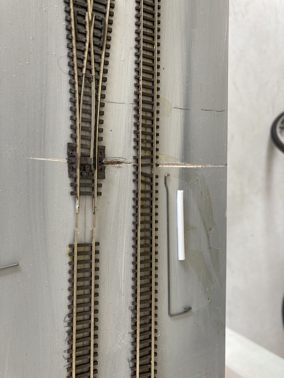
As the old bomb disposal line goes: "Cut the green wire...." Snip. "But first, cut the red wire." A clever tip I picked up from somewhere was to loosen the module joining nuts a little, then place a very thin sliver of cardboard or plastic between the modules and loosely tighten everything up before the track is soldered down and cut. Then after cutting, remove the card and tighten things up to remove the Dremel-cutting-wheel-sized gap between the rail ends left from making the track cut. 

Its also quite hard to cut the track vertical because the Dremel's fat motor body is a much larger diameter than the cutting wheel. You are often left with a V shaped cut. 

Fortunately, the second-hand Dremel that I have (its a Fuller one actually) came with one of those flexi shaft extenders which has a thin endpiece you hold onto, so this makes it a little easier. 


Other approaches: 

I suppose a jeweller's saw could be used if you had the track up on a decent embankment or a really thin wooden module end.

You could also simply butt cut sections of track together and stick them down, but I figured with my module mounting pins providing a reliable location during module mating (ooo, err), tracks that are soldered across the join before cutting should all line up perfectly every time. 


As an aside, a few subtle changes and liberties have been taken with the Studholme track plan for 'model operational' reasons.

The real place had, to the east side (to the 'right' of the picture below), a main, loop, goods loop/shed road, and a loop around that goods shed that I remember being used for fresh fruit. The Froot Loop as American cereal makers might say.

On the model, I've decided to move the goods shed 'east' one track, so that gives me a main, loop, another loop, and then the goods shed. That means I'll be able to practically have four decent sized trains crossing here (including the west 'island loop')without having to run through the goods shed (which was previously, per prototype, on the long eastern goods loop) or loop around the fruit track.  I've left one stub siding in to represent that fruit track, so a Z could be parked there. I doubt that this or the goods shed little loop would ever be used much in operations, but they do have reasonable large radius points for looks.


I made some subtle changes to my plans for the west (left) side too, with a siding that will have the wagon turntable into a seed store, and the coal merchant. This leaves a runaround loop beside the island platform for Waimate branch operations. I've also included electrical breaks so the 'Waimate branch' can be run using the DCC controllers being used for the rest of the layout, or by a separate (perhaps DC) controller. The track on the west side has two switchable and isolatable 'blocks' ... so... 
  • the island loop can be used by the main DCC feed for mainline crossings, while a branchline train comes into the runaround loop. 
  • or the whole island loop (right down to the far end) can be used for a Waimate branch train to come in, run around and shunt (including accessing the near end of the island loop)
  • or a mainline DCC goods could drop off wagons into the far tail of the island line for the Branch loco to pick up.
  • or the whole thing could be run by the DCC controller so that a mainline train could shunt the coal/seed siding.
I did consider having another point off the waimate branch to serve the stock yards, but decided against putting another point there. There's not much room, but perhaps a few fake rails might be laid in the grass there and a sheep wagon plopped on them.

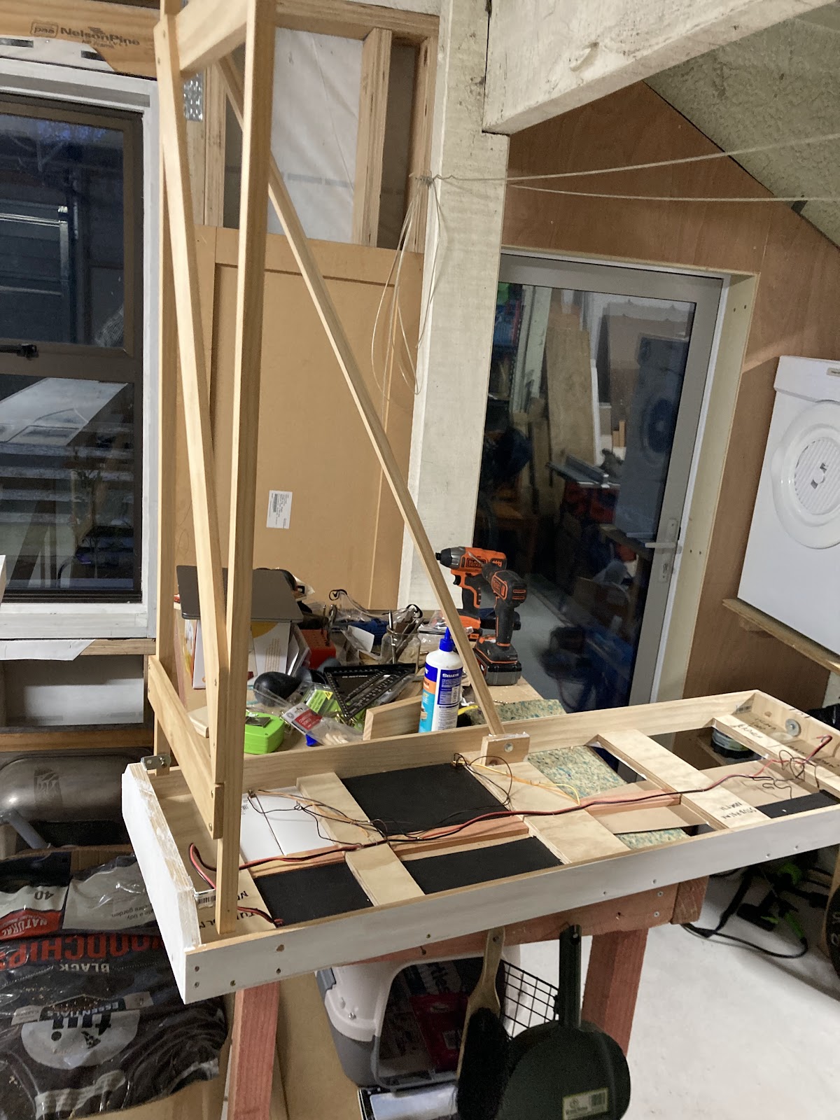
Seen from the other (north) end:

So there we have it. Some progress at last. 

Next, some more work on the points (three mainline points still need to be attached at the south end, plus the Waimate branch Y and curved point), some wiring, and after that (finally) the fun can start.

Wednesday, October 02, 2024

Studholme 9 - tracking it down

 DB says:

Studholme took a pause while life got in the way again, and also because of yet another mental block: how should one affix the track at the ends? My initial intention (and implementation) was to glue it down with contact glue, and the ballast glue would further lock things in place - as it seems unlikely that this will be dismantled or set up that often. 

Or would it? There would be nothing worse than showing up at an exhibition to find the track had been banged up. 

So I thought for a few weeks about soldering each rail to a brass screw and eventually decided to use the old PCB method, even though its a bit ugly. I still have one little rectangle of PCB left over from Otaki (!), but fortunately Jaycar still sells this stuff.

So let the next round of trials and tribulations commence. The first challenge is to cut the big square of PCB into more useful strips of the stuff. I vaguely remember scoring this in the past with a Stanley knife (a million times) and then snapping it off. I think Rhys said this stuff isn't great to power-saw because of the dust.

With the help of a few C clamps and some bits of wood I was able to snap off a few sections about 1 cm wide. A few some strips were then prepared for the first module join to be tackled, and the plastic flextrack sleepers cut away. This was challenging as I'd already glued the track down on this module end, and its always more fun on code 80 Peco track due to the way the lower half of the rail it set into the plastic sleepers. In addition, the PCB is slightly thicker than it should be, but I'm not going to let that bother me. In fact I liked the little undulations as the trains moved through Otaki.

I held the strips up to the track layout and marked the length and where I'd drill and countersink screw holes to fix them to the modules, and cut shallow insulation gaps through the copper with a razor saw.

And then screwed them down...

The near ones were subsequently removed and the holes countersunk a little deeper to hide the screw heads more. I hope ballast will cover the rest - I'm sure I did a worse job on Otaki.  Note the cardboard slivers between the modules in the above pic, we'll come back to them in the next issue.

This post was supposed to end with the joins all soldered up complete and cut, but this has been weeks in the making already, so I'll leave the soldering for now and get this posted. 

The final thing I did today though was to fill all the screw holes and paint the fascia. I went down to Mitre 10 looking for the Resene 'Bokara grey' recommended in the NZ120 Fremo specs and found two test pots, but that's $12 for 120 mls of paint. That won't last long. I then remembered we had some Friars Grey left over from roofing jobs. When I got home I also found we had some non-roofing interior paint in a similar shade so decided to use that instead. Its obviously a slightly different shade to Bokara, but I decided to waste that $12 on coffee and a scone tomorrow instead.


Will give it a second coat tomorrow. 

Sunday, July 21, 2024

Studholme 8 - All together now...

 DB continues:

Buoyed by the success of last night's bracing post, I went down to Mitre 10 and bought some 50mm M6 bolts and wing nuts and an assortment of washers, which let me complete the module's two legs with their fold-in braces. These braces are screwed to the legs at one end (with a bigger hole in one of the two bits of wood for some swivel) and M6-bolted to a little tab on the module at the other end. The braces are all made from the same 18mm square 1.2m long sticks that were procured from Bunnings for legs and braces when this all started.

This enabled me to sit the Centre module on its legs for the first time, with feelings of joy and a sense of pride that I expect a father feels when their first child takes its first steps. 

Like that child, the module was a little wobbly. Perhaps a little too wobbly for my liking, but at least it didn't fall on its face, throw up or poop itself. 

This wobbliness likely stems from the braces being relatively short. So a new plan was hatched: detachable longer leg brace sticks that can be stored within the module. So I decided to add the longest brace that would fit (diagonally) under the module 'lid' of the South module, with the module legs folding up to keep the brace in place during transit. This brace would be bolted with M6s and wingnuts at both ends.

This was proceeding to plan rather swimmingly, all too good to be true when it dawned on me that (six months ago) I'd put this South module's leg at the inboard end of the module, where it would mate up with the centre one with its two leg sets and leaving none at the outer end where support was needed!! D'oh! And I'd made a really nice job of this one too - better than the funky North module leg. Maybe this was supposed to be the module with two leg sets and not the Center one.....


So the wooden dowel pivots were knocked out - always use the correct tool (as above, "dear, where's the hammer?"), the leg was repositioned to the correct 'outer' end, and the brace added. 
This single brace felt a lot stiffer than the twin wee braces on the middle section. So now for the acid test... the South module was plugged into the Centre module. 

More pride and joy! So much so that I decided to reattach the legs of the North module (which I'd never been that happy with, but hey, they work) and put a similar long detachable brace on it, wingnutted at both ends. 


Ooooo. Finally, Studholme is back together again, and with those two long braces on the ends, it's actually pretty solid. The two end modules with their single leg sets are nice and light too. It all looks a little skewiff in the picture above, but the adjustable feet at the ends of the legs have since been wound in and out to level things up.

As an aside, I remeasured the length of the three passing loops - they should be able to hold a 2.1m train each. That sounds like a lot until I went inside to measure a pair of DXs and some bogie coal wagons. That is a 15 wagon train plus two locos. Maybe 16. 

Which again, sounds fine, but I already have a few more bogie coal wagons than that, with bits for another six. C'est la vie, whatever that means. If this ever sees any action at a show, and if it turns out to be a little short for the trains that want to be run, a medium length four track section could be added later on between the Centre and North modules.

Saturday, July 20, 2024

Studholme 7 - The quadpod

DB Says:

This blog post was started six months ago, but a other projects and a mental block have kept me from making much progress on the modules.

The first module that I started had some primer belatedly applied onto the bits that aren't tracks, and the single track arriving in from the north was cut square(ish) with the faceplate using an unruly dremel by your half-blind correspondent in the dark.

Results: Not completely terrible, but also, not as perfect as had been expected. Might need an expansion gap added yet on one side and its rail pushed closer to the edge. Having said that its probably fine as long as the adjoining module isn't similarly afflicted. I suppose cutting it a bit long and filing/grinding it back would have been more sensible.


The other tracks remain extended beyond the layout edge so they can be glued down to the neighbouring module in due course and then cut.


Another disturbing development at the north module set end was disclosed by the arrival of a passing set square: 


I think this is because the track isn't perfectly in the centre of the module at the very end. It might need to be swerved out to the right at the bottom of the picture. Fortunately it's only lightly tacked down.

Also fortunately, I haven't drilled the holes at the outer ends of the module set yet. Measure 8 times, cut once I think the old saying goes. 

....Then things stalled for six months with the mental block.

This is because at least one of the three modules needs to have two sets of legs, ideally the middle one, which would give me a setup like this:

But fitting two sets of legs, folded/stacked on top of each other into a thin module was going to be tough to fit, and Then Mr Pythagoras gets in the way when it comes to the angled braces, which I wanted to have attached and foldable for transit, but they should ideally be as long as possible.

So after putting off this task for months, tonight I went down to the garage and hammered out a thinner set of legs that fold up OK.  I even have a 'rest' for the lower legs to sit on (so they won't crush the upper ones) and will add a little twisty-movable 'key thingy' into it so everything stays locked in place during transport. As these three modules are intended to be stacked, I don't want the legs crashing down onto the buildings and scenery of the module below it.


It works! (not enough hands to take a picture and hold the legs at 90 degrees).

I then mounted my first angle brace (below). Just need a thin bolt with a wingnut to complete that, and then I'll build more using this idea for the other three leg sets.
A few thoughts on my spindly legs. They seem solid enough, but the proof will be when this is set up and used. Too much pressure on the wrong place could be a problem, with the holes drilled for the hinge pegs obviously the weak spots. We shall see. The thin legs have kept the modules fairly light, although this centre one with two sets of legs is getting heftier than expected. Still, it's completely self contained (carrying legs, braces and all).

Saturday, January 13, 2024

Studholme 6 - Legging it.

DB Says:

The Fremo120 standard has the tracktop height set at 1200mm above the floor and recommends having some means of adjusting this to account for build-tolerances and non-level floors. Something one would have thought unnecessary until I saw the surprisingly un-flat floors when we were setting up the big 9mm layout in Christchurch a few months back. 

So this means legs. If there was one thing I did like about the 9mm layout, it was how the legs folded up into the module, so everything was self-contained. 

While on my shopping expedition at Bunnings a few months back, I spotted these 1.2m long 18mm square sticks that might do for legs. They seemed tiny, but surprisingly strong when you lean on them, and my modules are not expected to be very heavy, or to be danced upon, and any force is coming vertically down, (horizontal force will tip everything over rather than bend the legs). 

So I gave them a pop. Out of about 25 sticks available, I selected the straightest 8. Look out for twists in the wood too, which can be a pain when you attach the cross braces.  Apparently cheap replacement wooden broomhandles make good strong module legs too but I don;t know where you find these. Maybe a dollar shop?

I've had a few iterations of legs and fixing methods during recent experimental months, so will just discuss my favourite method.

Basically the leg set is screwed and glued together, braced just so, and fellow Dandrufers will tell you that what looks like an exceptionally spindly setup is actually really solid (there is a little torsional twist, but that's not the direction of force that needs to be dealt with in a modular setup!) :


If you remember the old bomb disposal joke: "Cut the red wire..." snip. "But first, cut the brown wire" you'll know not to make one of these yet, otherwise it won't fold up into your module. Well mine didn't, twice.

Things to think about before you start carpentering: 

  • How broad will the leg set be ... presumably for stability, about as wide as will fit (make sure you allow for the broader width of your adjustable feet (and don't install those either yet)).
  • How will the legs be attached to the module? After thinking about and trying hinges and little steel L brackets (all relatively heavy, clunky, pricey), I reckon the same 8mm wooden dowels that I'm using to align my module set together is the ideal pivot. Strong, cheap, easy. I have used little bits of what used to be called 4x2 to put the holes for the dowels in. 


Consistent pivot locations using specific bits of wood to mark these out on my bits of 2x4. That's also the Bunnings 18mm x 18mm x 1.2m barcode FYI...
  • Related, where will the actual pivot point be located on the module? This was critical for me as I have fairly shallow 6cm deep module side fascias. I hadn't thought about this when I decided on 1200mm long modules, but you obviously can't fold 1200mm long legs inside a 1200mm module, especially when each end plate is 18mm deep, plus I need some pivoting room for the legs, so that eats up about 50mm of that internal space. Fortunately, you obviously don't need 1200mm legs as you can move the pivot point further away from the top of the track (probably why 10cm deep sides are preferred!) and as close to the ends as possible. This way your legs can be shorter and thus fit into the module when folded. Be aware that the  pivot hole in the leg obviously can't be at the very top of the leg or everything will snap.
  • From that, you can derive a leg stick length (taking into account the adjustable feet) and make sure that this will all fold up into your module... and most importantly, when you add it all up, it has the top of your track 1200mm above the floor when the adjustable feet are at about their midpoint of extension. 
  • Lastly, back to the bomb disposal men, if you build the complete leg set first and then attach it to the pivot... unless you have a laser-sighted CNC drill press, there is a fair chance it won't fold up into the module. This is because if you are out just a fraction with your drilling/alignment of the pivot holes, the two pivots won't be magically aligned in exactly the right place (and you have two dimensions to screw up in at both the module pivot hole and again in the leg hole). Thus when I attached and triumphantly folded my pre-made legs up, the pivots weren't perfectly square so one of the legs banged into the long-side fascia of the module top. So I now assemble the leg set in situ.

All of this made my head hurt for a week.

So what I have settled on is:

  1. make some calculations.
  2. cut/measure/drill my little 2x4 pivot pieces and attach them to the module (screw and glue) 
  3. calculate 1200mm less "track to centre of pivot (45mm for me)" less "allowance for feet in halfway extended position (25mm for me)". This is the distance between the bottom of the wooden leg to where you drill your pivot hole in the leg. I don't recommend doing it the other way around (drilling the hole close to the top and cutting off the bottom to suit) because its really hard to drill a big hole near the end of a thin leg without shattering the wood. I measure, gently clamp the leg together to be sure, drill the hole, then cut off the excess length from the top of the leg, and then apply some woodglue on the surfaces to add a modicum of strength.
  4. Cut the legs to length if you haven't, and drill/attach the feet, do a dry test or two before you make that final cut to make sure everything will fit. If you have a problem, you may need to rethink your pivot point!
  5. Drill good sized pilot holes in the delicate legs for screws to go through to attach the leg set cross pieces. Attach top and bottom cross pieces to ONE leg, not screwed too tight
  6. Dry apply the dowels to join legs at the pivot points (3/4 in with no glue).
  7. Fold the legs up inside the module and center them nicely (pack with wood against the inner faces of the module top) and only then attach the other leg to the cross pieces with the legs folded for as much of this operation as possible. Glue and screw everything for strength.
  8. Fold everything out and treble check you can get a level and 1200mm rail height before the glue sets in case you need to pull it apart to make adjustments.
  9. Fold the legs back in, attach the angled brace piece, and screw everything tight.

Somewhere in these final stages, you might chose to gently glue the dowels into either the leg (for strength) or pivot point. Be careful not to do both!

Legs extended. 


Legs folded cleanly:


How the calculations worked for me:


As for feet, I started with these relatively cheap ones with plastic press-in nuts, but the plastic nut bits broke off or lost their thread surprisingly quickly...

So have upgraded to these steel M6 T nuts gently hammered into the legs and these more robust feet below. You obviously need to drill two sets of holes in the ends of the legs first, one deep enough to take the T nut body, and one smaller diameter hole drilled more deeply to take the threaded rod when it is screwed all the way in (which it might need to be, to fold into your module).


One of my three Studholme modules will have leg sets at each end, and the other two will have just one leg at one end, with the other end being supported by the adjacent module.

...By the way, I've also put some coal in my two 3'6 LCs (at the far end) and added a ridge pole to an older one, plus experimented with colouring pencil on the KS doors with mixed results:

Quite like the way these four wheelers have all been resurrected and enhanced, with the possible exception of the LPA with the badly applied tarp, which I thought was 'clever and quirky' at the time, but now is just 'annoying' me.