Showing posts with label Track. Show all posts

Saturday, May 03, 2025

Elmer Lane 25 - Module End

 DB returns:


A little progress has been made in recent days at the north end of Elmer Lane. I finally made the decision to install the 'Greymouth platform-to-loop' turnout here. The original thought was to have this on the next module, thus keeping the 'Hokitika line' track, which runs in front of the depot and then circles around behind it, clean and clear of complications.

After a bit of measuring of my current, and extrapolating out to my 'desired' TranzAlpine, I reckon it might have been a bit tight. Moving the turnout onto this module probably gives me two extra car lengths if required. You can never have enough storage space.

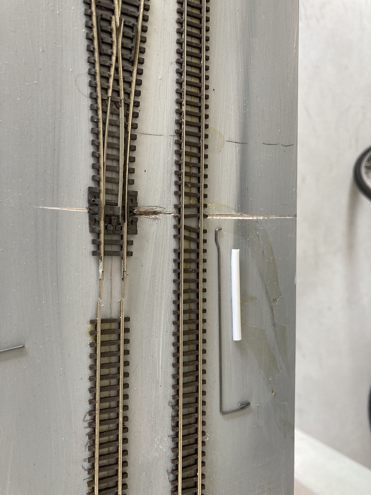
Installing a turnout at this late stage also requires putting in a control rod after all the other tracks are well in place and ballasted. The rod runs just beneath the surface of the baseboard in a plastic tube and seems to work fine in tests, although I haven't attached the spdt switch to power the frog yet.

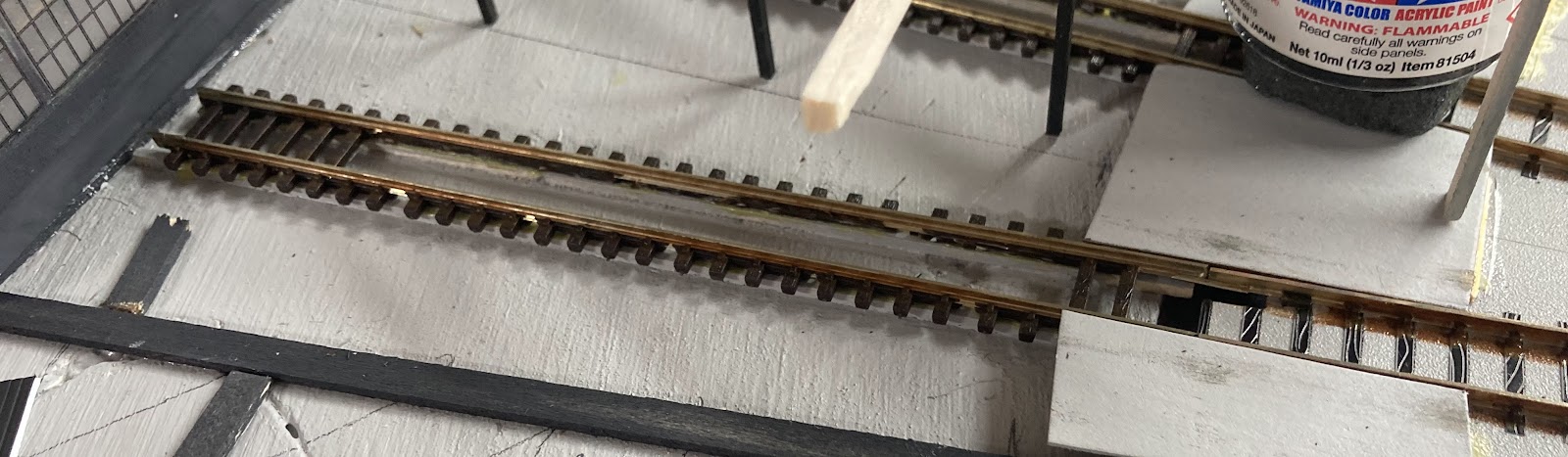
But I did cut a strip of copper-clad PCB, scored and drilled it in the right places, and attached it to the edge of the module. The platform road, loop and depot access track were then soldered down to it, and some feeder wires put in place. With the extra track, the track spacings are a little tighter than I like, but there is plenty of room in tests with my largest vehicles (SpaceRacer, GT, DM)

With that done, and the last of that track paint squeezed out to cover the new sections of rail, the last of the visible tracks could be ballasted.

The day ended with me 'pottering in the garden' to the west of the Hokitika line, planting a few trees, bushes and grasses.  While a few of us have bemoaned the closure of various 'local hobby shops', it seems that a slight salvation seems to have come with a resurgence in wargaming and kitmaking. There are now three or four gaming or art shops in Dunedin that now carry paints, glues, decalling supplies, tools and scenic materials. I've picked up a few packs of 'Gamer's Grass' recently. Its like the old Silflor tuft stuff, (I still have about 80% of that Silflor left) and Gamer's Grass available in a reasonable variety of realistic, plus a few fantasy shades, and different lengths too. Its a lot cheaper than Silflor used to be too, at between $12-15 Pacific Pesos for a section a little less than 20x10cm.

I like being able to mix the various shades and lengths in a given area. I believe you can make these blobby grasses yourself on a piece of wax paper if you have a static grass machine, but for the rest of us, the occasional visit to the hobby shop can't be beat.

I like using these tufts to make cabbage trees too, using old twigs, or in this case, bits of a Woodland Scenics brown plastic tree armature with bits of blobbygrass attached to the ends. As was learned on Moana many years ago. Four little cabbage trees were added, and here's the worst of them:

Sunday, March 02, 2025

Elmer Lane 17 - scenery unfolding

 DB says:

A basic scenery layer has continued to invade Elmer Lane.  But before ballast could hit the roundhouse tracks, they needed to be wired up and a few joints soldered. I've now wired 9 of the 15 roundhouse tracks, heading clockwise from the one next to the boiler house. This includes the tracks opposite the four arrival tracks on the other side and the two little stubs by the foreman's office if that makes sense. 

This is ugly, but it works, most of the mess is is hidden by the roundhouse, and its so much easier than drilling individual droppers down to below. I'll paint the wires the same Harvard Grey as the floor. I've also fixed up those two little stub tracks over beside the office that I'd inadvertently only wired up one rail on.

There was a plan to have on-off switches allowing power into two clumps of three tracks each for the remaining six stalls. This would enable three or six tracks to be electrically isolated - to display non-DCC locos, or even to give DCC locos a rest 'off-the-grid'. I'm not sure I have the energy to do this but we shall see. I might just leave a few completely dead. I will at least power the track inside the end 'wall of windows' as things will look pretty good going into that stall visible through the end wall. 

Another thing we noticed on the modelling day was that on the real Elmer Lane, the sleepers aren't really visible, there are ballast fines everywhere. Here the sleepers stand out, being dark black. 
I tempered this slightly by putting a wash of light grey+brown over them and think this looks a little better. The yard will also be weathered once the ballasting is completed.

Having a bunch of ballast between the rails can get messy in the flangeways, and the few tracks I have here with plenty of ballast on the outer sides and little in the middle look odd, so I'll probably keep the main approach tracks looking tidy as in the pic above.

Ballast has spread far and wide and some green is going down:


Although this isn't a 'countryside' module, there is a little green about, beside the Hoki line, around the back of the roundhouse, and in a few spots in the depot itself. Some low-relief 3d greenery and maybe even some static grass will make an appearance. I think the little hut visible at the end of one of the wee stub tracks was a RhysCasting. It was once on my Moana module.

I even discovered a well-traveled mini-cabbage tree from Moana in a box of scenery bits, so it has been installed too.

Here it and the hut as they were on Moana:

And now further west along the rails at Elmer Lane:

A pile of lighting-up wood was started on one of the stub tracks, made from offcuts of that basswood. Some had grey on one side, some black, so that gives a little variety through the pile. Its been added too since.
Then some soldering of fishplates enabled the strips of 'concrete' to be laid between the tracks and ballast laid:
And some overall views as ballasting has progressed and some of these locos have seen the forst sun in many a year.


Monday, February 03, 2025

Elmer Lane 11 - on a Roundhouse Kick, and Tidy Track painter pen review bonus

DB bumbles onwards:

I've been chipping away at the roundhouse for a few days here and there. When I started, it felt like this would take months, but progress has been fairly rapid.

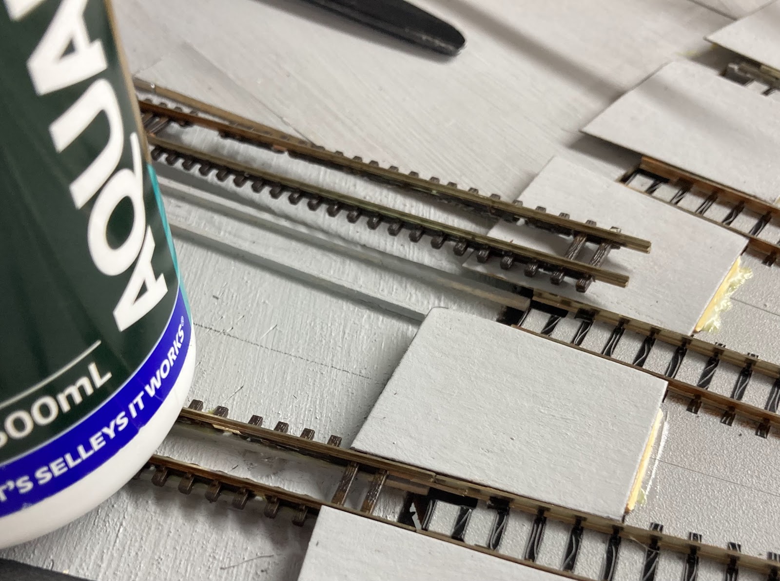
A quick aside, and a little out of order, but I wanted to paint the track, as I reckon this looks good. I've done this with Rustoloeum spray cans in the past, which  is OK if you keep away from points, and hand painted my Z scale double tracker, but that's slow work. 

A Woodland Scenics 'Tidy Track' painting marker was procured last time I was in Christchurch as a novelty. Pretty pricey at about $23, but I thought it might be useful for some of the tricky bits. As track painting was nearing the top of my list of things to do, and there is a lot of tricky fan trackage, it was opened up for a try. 

Its a paint pen with a fibre tip that is spring loaded. You shake it up (with a little ball inside) press down on the tip a few times and it should paint. 

I thought mine was broken, because after shaking it for forever, and pressing on the tip again and again about 100 times, eventually a little brown discolouration appeared at the top of the tip. This eventually seeped its way down to the point and away I went. 

Initial thoughts: mmmm, not great, the hard fibre pen tip bounces off all the moulded track spikes, so there's not great coverage on the rail. But soon enough the tip starts to fluff up a bit and it starts covering nicely. It started humming away along the Peco 55. The Kato unitrack turntable pieces seemed to have sharper or more pronounced spikes, which tore up the tip more. As I went along, I wiped the tops of the rails with stripwood, to clear off the brown paint on the rail heads.

Eventually the tip got so fluffy as to be useless, but fortunately there is a spare in the package. 

I figured the pen might do some of the fan tracks and be an expensive and pointless experiment, but it covered all the track on the module, including the yet to be installed Hokitika balloon and straights, and most of the track was done on both sides... and I haven't run out yet. Its not the most precise weapon that exists, so I'll hand paint the turntable bridge rails, but its pretty quick once you get into the swing of things and a good colour. 

Final verdict: I'd do it again.

As for the roundhouse,  there are a millions ways to pat this proverbial cat, but I decided have the whole thing lift-offable so it can get carried in a box and not get smashed in transit.

The first step was to build the internal wooden pillars, as I figure you'll see them through the open doors. A jig was made, since I have to do everything 15-30 times! This is below in foreground of the pic here, made from some offcuts... and the output (an unpainted roof beam with three dark grey legs) between the DI and the roundhouse.

The roundhouse walls were stuck together in about the right places and then the leg sets were supported in a more or less vertical orientation and glued to the rear wall....


Random stripwood bits were then haphazardly glued across the tops of the unpainted beams to tie things together. Surprisingly this is solid and the whole roundhouse is pretty light so far.

About this time I was also adding 3mm sheet basswood under everything to bring the legs and track up to a consistent height, but the less said about that the better. It was painted the same concrete/Harvard grey as the module top.

Then some thin card 'concrete' was poured in a ring around the roundhouse fan tracks. Supported by stripwood. 

On the two most 'visible' roads to the 'left' by the crew buildings, I decided to put in some 'pits' by cutting out the sleepers.

Gluing the track onto some little 2x2mm strip

And painting the inside black.

We shall see if this is a good or stupid idea, but it didn't take long. 

The roundhouse progresses:

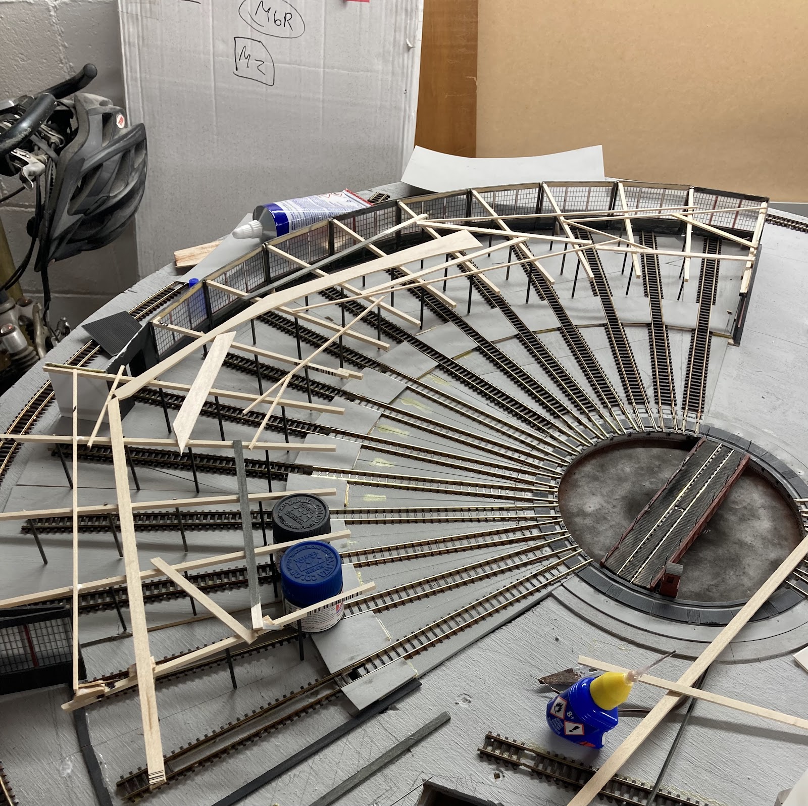
A little like the real 18 stall thing curtailed, this has are 15 to make it about the same shape as the original. Two normal bays to the left, then three longer workshop roads (the building should be twice as deep but here, but I have only room for 5-10cm), then one track that continued outside through the back wall of the roundhouse (the three workshop tracks and this through one survived as a 4-stall roundhouse through the 80s) and then I have 9 more normal bays to make 15 (the real one had an additional 3 normal bays to the right, but their bays were all more closely grouped - I'm stuck with the Kato turntable angles/spacings). All my 'regular' bays (11 in total) have nice back windows, the workshop bays have plain walls.

Front face vertical pieces have now been installed (Mitre 10 stripwood prepainted light grey):

These vertical pieces have now been joined with the start of the front face woodwork above the doors (the same ribbed plastic, prepainted light grey and weathered slightly since I don't have a local hobbyshop selling Evergreen styrene/balsa etc, and I'm too impatient to wait until next week):


And again the whole roundhouse is light as a feather, but its quite strong and and can be lifted off if work needs to be done - the track painted or cleaned, or the workshop floor weathered, as will come. There are several locating 'bumps' glued to the module that but against the roundhouse walls to ensure it is positively located in the same spot every time it goes flying and then returns. There is also a dark grey 'foundation' glued to the module that the roundhouse sits on. This will let me ballast up to that tidily without getting glue on the roundhouse itself. 

Monday, January 06, 2025

Elmer Lane 3 - real word curve testing

 DB continues:

So, Elmer Lane, with a more-than-180-degree balloon loop, all able to be squeezed into a car... Well the whole turntable and roundhouse thing wouldn't work very split down the middle across two modules... but is it practical? There's only one way to find out.

Lengths of second hand Peco code 55 flex were unearthed and the soldering iron fired up. It only took one joint at the head of the curve, the other pieces of straight flex were just fishplated in. The curve had four or five staples applied to keep it tight

Then the Digitrax DCC was dug up, it took me a few minutes to remember how it all worked, but soon enough, some of my DCC locos had what might be their first real spin in about 13 years. 

First up was the challenging test train: a light 1990-built LC up front with a glued-stuck Microtrains coupler (connected to a long body-mounted DX coupler that will want to throw out on the curve), some lightweight four wheel and bogie wagons (all with fine flanges), including a KP with a loose weight rolling around inside it, the light and long GT car carrier, my new flat UK and the featherweight laser cut plastic ZH, and then at the back, heavyweights and top heavy wagons - resin castings and the new Trackgang Zs and old CF. This pic taken just before coupling up for the first run.

And... no drama to report at all, except I could only get one of my DXs running at first, so it had to take the train, alone and slowly. Success! 

Then when trying to push it back around, a stall, with the middle of the train in the middle of the curve, and the DX's wheels spinning. But no derailments. I knew this floor wasn't level,  but I didn't realise quite how much. Some books were employed to lift one corner a bit, but to no avail, the mighty DX was beaten on the uphills.

The day was saved by DG 2376, on a heavy Kato PA-1 chassis. Man that thing can haul. Up and down no problems. It was only when packing away the train it was found that my GT has a splayed bogie, so the one wheelset that was left on the track when I picked it up probably wasn't rolling at all. 

After this, it seemed like a good opportunity to play trains. something I don't do enough of.

Here's the single DG on a coallie. The heavy CBs are in the middle (they have pizza cutters which rub on the metal wagon floors), and an even heavier Trackgang CF is at the back of the lightweight CWs. No dramas pulling or pushing uphill at quite decent speeds. This train looked nice behind the two KiwiRail DXs when I got the pair running and multiple-united together, although they run slow.

Not entirely prototypical, maybe the DG should be blue

The TranzAlpine then came out, and this is a pretty heavy train with a high centre of gravity as the cars are solid resin, but they have nice metal wheelsets, so I had no qualms with the DG and later the faster DFT pushing this uphill around the curve at unrealistically high speeds. 

So the verdict is that even my creakiest old wagons in a worst-case consist seem to run fine around this sharpish curve. And so they should really, this is flextrack laid out in a smooth, flat circle with a single soldered join, and an 18 inch/450mm radius curve isn't crazy tight. With a more sensibly-ordered train (heavies at the front, free-rollers at the back), I can't see this curve being a problem unless there is way too much speed and herky jerky operator error.

More worrying was that many of my locos didn't work, or took a while to get working, or barely worked at all.

A few may have an incorrect address programmed on the decoder for some reason, such as DG 2330 and DJ 3067, both of which were DCC-ised not long before all this stuff was packed away. I didn't think to get out a programming track to see.

None of the Atlas SD35 chassis under the Da/DBR/DCs worked well. Cleaning and better electrical connections between the decoder and metal split frames are required, although I did have DC 4559 and 7132 (both blue) on the Tranz for a while. 

DF 6277 and DX 5448 ran jerkily, and DF 6064 could barely turn its motor with lots of humming, so something must be binding in there. These are all old Kato chassis with decoders that were hardwired in 1995 for my little 'Wellington' layout, built after I purchased the Digitrax. Amazing to have an electronic anything that still works after 30 years and will even drive modern decoders.

The two KiwiRail DXs on Atlas Dash 8 chassis with clip-in decoders are nice and smooth, but must have their VMax set quite low, perhaps to run with slower locos? Their maximum speed at 100% is preeeetty slow. That should be fixable easily.  

The stars of the show were undoubtedly DFT 7132 and DG 2376. And the curve. 

.....

However, I don't want to get too distracted by this until I have finished the hard work of Studholme...

Friday, December 27, 2024

Studholme 12 - pointed comments

DB pointedly comments:

Studholme got moved from the garage into the basement yesterday, and this was quite easy, even with the legs extended, because each module is really light.

One of the last remaining tasks to be done on the 'northern end' before the fun can start, is sorting out the three 'mainline' turnouts. As discussed in a previous episode, the odds and sods points in the yard are as-is Peco points, sometimes operated with manual-remote pushrods, some just with your fingers.

But in an attempt to make the mainline ones more reliable, I have DCC-friendlied them. This is a bit of a misnomer, as they will still make DCC freak out if you travel too far off a siding into a set that aren't set for you, but it prevents metal wheels shorting out between the main outside rails, the closure rails, switch blades and frogs that might be at different polarities.  It also ensures there is a really positive feed of power into the frog, whereas with the standard Peco setup, this depends on the point blades being clean and making good contact with the outer rails. Sometimes that cleanliness can be upset by ballast and glue, and dust and general gunge. Whatever that is.

This process can be done several ways, but I :

1. Cut the inner rails to isolate the frog from the points blades.

2. Linked the 'points' ends of these to the adjacent main outer rails (so the points blades will always have the same polarity as the outers next to them)

3. Feed the frog (and the frog-end of the inner rails) with the appropriate polarity depending on whether the turnout is set for 'normal' straight-on running or 'reverse' for the curved track.

Cutting the rails was done using a jewellers saw (incredible things.... I got mine from the same place King Druff did many years earlier). Wiring was done with what looks like a blowtorch. This was actually done almost a year ago, and I've since procured a less-agricultural soldering iron, one that actually has a pointy tip! Below, plastic has been removed with a razor saw, with the joins about to be welded in:


The frog power feed comes from a SPDT switch - I bought a dozen of them from the local Jaycar and drilled them out to accept some piano wire. This way, when you move the switch, it puts the right polarity into the frog, and it also physically moves the point blades via the piano wire.
The piano wire for the first turnout was formed in a clever manner to sit alongside the ballast and under the turnout in a slot- I'm not sure if this was a good idea or not - the others are routed under the 'baseboards' and simply have a vertical bend that sticks up through the hole in the Peco throwbar.

Slots for the piano wire in place, and also for the power feed to the frog before sticking down the turnout:


You do need to enclose the piano wire into something (plastic tubing is ideal) that is attached to the layout or the wire will flex when pushed and might not move the points. And here a bit of foamboard  baseboard stuck on top:
To fill in gaps where sleepers have been cut off to take rail joiners, the sleeper offcuts were cut into 'ends' and middles' ...

and badly glued in the middle and outside the rails to tidy things up, otherwise these missing sleepers can look a bit naff.

So that was the first mainline turnout done, for the next two, the pushrods were simply routed under the layout - below are two switches with their bits of piano wire which are disappearing into a plastic tube:


Ignore all the setting glue there...  And below, the piano wire emerges straight up at the points end, here before the excess wire was trimmed off the top:

In between the switches and turnouts, the wire is held in plastic tube. This has a slightly unusual routing arrangement:


As I had fixed the Peco turnouts in place (because the track centrelines had to be located 'right there'), and also fixed the SPDT switches in place (because they had to be attached to the solid wooden edges of the modules), the actuating wire between them has to be just the right length to operate the points properly. 

Bending the stiff wire perfectly is quite hard to do after the fact, so my wires were both slightly too long for the switch to operate the points in both positions. The solution was to 'make the wire shorter' by having it travel further, hence the little bits of glued plastic forcing the tubes down and taking up some of the slack. These little spacers of of white plastic were done with trial and error (mainly error) underneath the baseboards until the points operated nicely in both normal and reverse positions up top.

Tuesday, December 10, 2024

Studholme 11 - more trackwork

 DB says:

'The schedule' allowed a few hours back on the Studholme modules today. 

It has now been more than a year since I started this, further cementing the blog's status as holder of the Guinness record for longest-average-elapsed-time module builds (thanks also to Paekakariki and Waihao Forks). Clearly long gone are those youthful days of blitzkrieging up a module in a week.

Its been a warm 10 days down here on The Mainland, and a kink revealed itself upon my arrival. Half a mm of rail was taken out of that track and the thing reconnected. All the other tracks seem fine, as a little space was allowed for this in the rail joints.

Some manual point controls have been added to the points on the Waimate Branch (backdrop) side of the layout. 

The three 'mainline' points at either end of the module set will be the most used, so are being made DCC friendly (whatever that means) and each is controlled by a slide switch discretely mounted at the side of the layout, via piano wire.

The four other points on the branch side are 'as-is' Peco points, controlled by more of this chunky piano wire and covered with some oversized tubing in a most agricultural fashion. speaking of agricultural, I see the code 55 Waimate Junction Y here still has some code 80 tails soldered onto it from its last use! They remain in place as the only code 80 on the modules!!

The three points on the other side (east side with access to the goods shed and fruit siding) are as-is with no remote control at this stage. I doubt they'll be used much, but if they are, I suppose I could work them with some actuating wire under the module.

So track has today been fixed down right up to the three south end mainline points, which I still need to make DCC-friendly. The coal/seed siding was also spaced further out as it looked a little close to the others. Darryl P suggested extending the coal/seed siding to serve stockyards there, which might be feasible. I certainly want to have the Studholme Hotel modelled as a flat, and the stockyards should/could be to the south of this, and a good way of fitting something small into the thin gap between the branch's curved point and the backdrop. We shall see.

The 2010s-era 17-wagon coal train was laid out on the loop to check sizing. As predicted, the loop is about 10cm short, so I'll have to drop a wagon if I want the train completely ensconced, although a train this length would be fine in reality, as it's in and clear clear of the mainline for crossings, and an oncoming shorter train can safely run into the siding (closer to the camera in the pic above), although some shuffling of the coalie for-and-aft might be required to let the shorter train out. In hindsight I should have positioned the mainline points out closer to the ends of the module set, but its a bit hard to move them now.

Friday, November 15, 2024

Studholme 10 - Cutting the cords.

DB follows on after a pause - this post has been in draft form, occasionally appended to, for the past six weeks. 

The Studholme module build has been a bit drawn out and higglety pigglety with all manner of things occurring out of the ideal sequence. Here is an attempt to get things back into a more sensible order of operations.  

Its always a good idea to paint the trackbed/scenery so if any ballast falls off there won't be white primer showing through from underneath, so this was done, as was filling in the remaining holes in the baseboard framing with foamboard. 


After these pictures, the track centrelines, obliterated by that recent application of grey paint, were redrawn.  

So finally things are at the state they should have been before any track was laid many months ago! Now feels like a good time to put down more track and start soldering it down across the PCB joins. 

As the old bomb disposal line goes: "Cut the green wire...." Snip. "But first, cut the red wire." A clever tip I picked up from somewhere was to loosen the module joining nuts a little, then place a very thin sliver of cardboard or plastic between the modules and loosely tighten everything up before the track is soldered down and cut. Then after cutting, remove the card and tighten things up to remove the Dremel-cutting-wheel-sized gap between the rail ends left from making the track cut. 

Its also quite hard to cut the track vertical because the Dremel's fat motor body is a much larger diameter than the cutting wheel. You are often left with a V shaped cut. 

Fortunately, the second-hand Dremel that I have (its a Fuller one actually) came with one of those flexi shaft extenders which has a thin endpiece you hold onto, so this makes it a little easier. 


Other approaches: 

I suppose a jeweller's saw could be used if you had the track up on a decent embankment or a really thin wooden module end.

You could also simply butt cut sections of track together and stick them down, but I figured with my module mounting pins providing a reliable location during module mating (ooo, err), tracks that are soldered across the join before cutting should all line up perfectly every time. 


As an aside, a few subtle changes and liberties have been taken with the Studholme track plan for 'model operational' reasons.

The real place had, to the east side (to the 'right' of the picture below), a main, loop, goods loop/shed road, and a loop around that goods shed that I remember being used for fresh fruit. The Froot Loop as American cereal makers might say.

On the model, I've decided to move the goods shed 'east' one track, so that gives me a main, loop, another loop, and then the goods shed. That means I'll be able to practically have four decent sized trains crossing here (including the west 'island loop')without having to run through the goods shed (which was previously, per prototype, on the long eastern goods loop) or loop around the fruit track.  I've left one stub siding in to represent that fruit track, so a Z could be parked there. I doubt that this or the goods shed little loop would ever be used much in operations, but they do have reasonable large radius points for looks.


I made some subtle changes to my plans for the west (left) side too, with a siding that will have the wagon turntable into a seed store, and the coal merchant. This leaves a runaround loop beside the island platform for Waimate branch operations. I've also included electrical breaks so the 'Waimate branch' can be run using the DCC controllers being used for the rest of the layout, or by a separate (perhaps DC) controller. The track on the west side has two switchable and isolatable 'blocks' ... so... 
  • the island loop can be used by the main DCC feed for mainline crossings, while a branchline train comes into the runaround loop. 
  • or the whole island loop (right down to the far end) can be used for a Waimate branch train to come in, run around and shunt (including accessing the near end of the island loop)
  • or a mainline DCC goods could drop off wagons into the far tail of the island line for the Branch loco to pick up.
  • or the whole thing could be run by the DCC controller so that a mainline train could shunt the coal/seed siding.
I did consider having another point off the waimate branch to serve the stock yards, but decided against putting another point there. There's not much room, but perhaps a few fake rails might be laid in the grass there and a sheep wagon plopped on them.

Seen from the other (north) end:

So there we have it. Some progress at last. 

Next, some more work on the points (three mainline points still need to be attached at the south end, plus the Waimate branch Y and curved point), some wiring, and after that (finally) the fun can start.