Showing posts with label Ed loco project. Show all posts

Monday, October 11, 2010

In the mail

The nice thing about going away is coming back to a full mailbox. Apart from the bills (and no Journal envelope) there was also a small envelope from mr McHarg with the latest order of plates. Last night I set about putting the first ones in place. These were for the Ed's, and I've recieved 104 and 109 (I had numbered mine 107 and 110). So, guess which numbers are hardest to paint freehand?(well, not quite true, but 0,1 and 7 are the easiest)


Unfortunately the artwork for the distinctive makers plates is lost, so I didn't get those. Guess I'll be making an attempt to do it myself.

The photo dirama is backed with a photo from some website and is a black and white shot of the main street of Paekakariki in the mid 1950's. It looks a bit odd, but when I switch to grayscale I think it will be very effective (well, when the road is in place as well).

Saturday, November 28, 2009

Its almost over

All of you out there in reader land will be most relieved to know that the ed project is nearing its end. About the only job left was to do the painting (well, almost).

I had started off with a red oxide colour for the undercoat. I chose this to skew the top coat colour towards the darker more burgundy shade of red (at some point I'll do a more involved post on this).

After the base coat we move into the layered weathering system I've described before. a couple of coats of thinned out Tamiya 'Smoke' later, and we get to this sort of effect.
One thing that wasn't quite working at this point was the grill side of the loco's, as the paint was not settling in some areas to the degree that I wanted, Most noticeably the side vents and the small grills along the bottom. To fix this I put both locos on their sides and applied the wash just to these spots. problem solved.
The underframe didn't look quite dark enough and so this area got several coats of undiluted Tamiya smoke which seemed to do the job. After all this I laid on a coat of matt varnish to get rid of the gloss colour

Drybrushing was rather muted for these locos as they were relatively 'clean' due to the lack of steam locos in Wellington in this time period. In this case they just got a very light drybrush of chocolate brown on the lower sides, and a light drybrush of leather brown on the roofs. This seems to give about the right effect.


I also managed to hand paint the numbers on the headstocks. The missing bits are the cowcatchers (buggered if I know how to do these, soldering wire and brass failed completely)and couplers (which is a re-occurring theme and something I really need to fix soon).

To get away from Ed's and guards vans, are there any other modeling topics that people would like me to cover? All reasonable suggestions investigated, otherwise it will be onto some meat vans or even more guards vans.
Its your choice.

Thursday, November 26, 2009

Handrail time

As well as spending a few days banging my head on a variety of well built baseboard bits under my friends layout, I've also spend some time at my bench, and as usual, its back to the Ed's again, as I would really like to get them 'finished' in the not too distant future.

I had been avoiding a few detail jobs on the ends. the first up was the front door surrounds. I cut a piece of paper to size and then carefully cut out the inside with a sharp knife to give a retangle with lines about 0.5mm wide. This was then glued into position with PVA.


Next up was the handrails. faced with having to bend multiple numbers of these to size i came up with a small jig. I used an iron spanner that came from one of those flat packed warehouse furniture kits. using a hacksaw I cut in to both sides until the center bit remaining was the right length to fold up the hand rails.


It was a relatively simple task to bend one end of the wire with pliers, then fit it into the jig and bend to the correct length. To cut to the correct length I used a triangular file to cut is off on the other side. pliers bend the second end to the correct angle, and there you have it. as you can see from the jig there are 2 different length handrails. These were the vertical ones. For the horizontal ones I just cut some wire to length and then glued it in place. It looks OK from 2'.

Friday, November 20, 2009

Topping it off

With almost all of the body work done I had a crack at the roof bits of an Ed. Pictures from Amateur fettler and Cabbage shows there is not that much up there (sounds like the top of my head) apart from the pantographs, so it was quite straightforward. There are 4 metal sheets under the pantographs at each end which I assume is to strengthen the roof so that the fitter won't fall through while trying to fix something. There was a bit of bendy pipework at one end, and this was folded up out of copper wire.


The other end has a straight bit of copper wire and another flat steel sheet. This area was once the roof for the steam heat boiler before it was removed, and so I placed a small patch in the center where the funnel would have poked out.
The only really complex bit is in the middle

There's a set of 5 isolators and a bus bar of some sort. this is obviously where the electricity gets in. I cut up bits of plastic round rod and glued them into place. I did actually have a crack at turning the shapes up, but my knees gave out.


So, after all that we have a roof that looks close enough to the real thing.

Wednesday, November 18, 2009

The masked loco

More work on the Ed's today. It was finally time to tackle the hardest parts of the model; the ends.

The Ed has a rather complex shape at each end, that was once described as having all the aesthetic qualities of an upturned bathtub. The sloping fronts make it extremely difficult to get the windows square as they have to be a trapezoid in order to look square from the front. I would love to say that I sat down and let my inner finescaler calculate out all the measurements to several fractions of a millimeter. the rest of me said sod it, tied him the a chair out the back and started cutting. I started with a piece of paper that was the right height. The center window was measured out as well as the starting points for the inner corners of the larger windows. I then carefully shaped the bottom of the paper to the front of the Ed and carefully cut the paper back till it was a square fit. I then measured out where the outside of the windows would be and joined them up and cut it out with a very sharp knife. I used this as a template for the other 3. Yes, it was indeed a prick of a job. These were then glued into position with superglue. This operation is not for the faint hearted, slow witted, fumble fingered, or anyone with an allergy to superglue fumes (I qualify in several of these categories, though I'm not yet allergic). The edges were smoothed back with a file. I also added the cab sides without the doors.

The next fun job to tackle was the headlights. The Hutt built machines were fitted with a cowled headlight that looks beautiful. Its another one of those 'How can I make this harder for a modeler' bits. So, how does one turn up a cowled headlight without access to a lathe when the only thing one has that is the right diameter is a thick heavy bit of brass rod?

'I'm also playing the harmonica and banging a drum as well'

A piece of brass rod is cut off and chucked up in the power drill. This is then clamped between the legs with one leg operating the trigger. The hands are then free to use a variety of files and hacksaw blades to do the shaping. I then used various grades of sandpaper to clean up the tool marks. The brass surprisingly doesn't generate much heat as its all being disipated by the drill chuck.

You will notice that I have not done anything to add a working light. This is just due to the fact that I find lighting beyond me. It always looks wrong and I can't seem to get it to work right. Its also one less thing to go wrong on the layout.

The base of the cowl then had to be shaped to fit the curved end of the cab. This was achieved using a large round file I have owned for 15 years especially for this task.
When I had removed enough brass I then glued it into position with superglue.

The second one was then finished using the same methods.


The Addington built machines just had a plain headlight. this was just cut out in the drill using a hacksaw. At least someone on the mainland was thinking straight.


As you can see from these pictures I have also added the roof walks. I was not sure how wide to make them, and in the end made them 2.5mm (1' in scale) as that was the narrowest board I would have walked on at any height, let alone that height. I have also painted the outer roof and the windows. I have yet to actually glue the pantographs in as I'm just waiting on some pictures of the electric bits on the roof of 101 so that I can add that detail.

They do still look butt ugly

Wednesday, November 11, 2009

What lies beneath

Now that my Ed project is back on track, I have started looking at the jobs that need doing to get it finished. Todays session focuses on the undergubbins. I started off by making the sandboxes. These were cut out from a 3mm strip of 2mm thick plasticard to the right length (8 of one and 4 of another, plus a spare for each). I made the cuts to shape the bottom of the boxes, and then glued some 1mm wide strip on top for the filler caps ( I think they are supposed to be round, but its hard to see under there in any of the photos I have anyway). Finally I glued some round bits on the bottom cos they were there too. Not sure If I'll do the sanding lines yet, they are just asking to break.


Full of the enthusiasm I then made 18 axleboxes to glue on. just a rectangle of 0.5mm plasticard with a 2mm diameter bit of round plastic. I have glued these where they should be rather than in line with the (slightly) incorrect wheel spacing. It's hard to tell that they are not lined up correctly from most viewing angles. I probably should have made a mould and cast all these things, or even had them RP'ed and cast in brass or something, but it was nice to sit at the workbench and churn them out (while watching 'Top Gear' on TV).


After all this I filed the axleboxes so that they were all square, and then added the axlebox retainers at the bottom. These were cut to length from 0.5 by 1mm strip and glued into position


The final step tonight was to add the (well I think it is ) emergency signal trip doodad. I have only seen this well documented on Paul Berntsens model of 101 in the journal, but theres enough photographic to suggest that there is some sort of device in that position, and the rest of the underframe is remarkably uncluttered, so its probably correct.


And this concludes the underframes. Theres only a step to add at one end on each side. I'm not doing the underframe cutouts as they are in the too hard and not seen easily box. My inner finescaler is slumbering quitely in the corner as I type.

Saturday, November 07, 2009

Electric blues

I have a bit of a problem with my modeling sometimes. As it turns out, I'm somewhat of a perfectionist (those of you who know me will be somewhat surprised at this admission). Perfectionism takes many forms (I read it in a student pamphlet so it must be true). my particular cross to bear is that I often struggle to get something started if I don't think it will finish out the way that I want it to.

Cut to something that makes sense. My Ed project has been stalled for a month or so as I was not sure about how I was going to do the ends. These are a complex mix of geometry stuff and I was really not looking forward to them. Fast forward to the current modeling bench session and I'm looking around for something that does not involve guards vans and might actually finish some of the 1/2 complete projects on the bench.
I started off by cutting a strip of 0.5mm plasticard about 1mm over the height required for the front. Measuring off the plan gave a 5mm flat front piece, and I added in about 8mm for the bent back front bits, and then cut 4 pieces of plasticard to size. I scribed some lines into the back of the plasticard and then bent the front plate slightly. I chamfered a small bit of plastic of f the side panels. these were then glued into position and left to dry. I rounded the corners with a file. Suddenly flush with this massive break in my psychosis I then leapt on and started with the roof. The Ed has a recess in the roof where all the electric bits fit, that I decided to emulate by laminating 2 pieces of 1mm plasticard together. The first piece was just a flat plate measured up off the body dimensions. I first sanded the top of the body flat by rubbing it on a piece of flat fine grade sand paper, and then glued this first piece into place. Smaller rectangles were then used to form the second layer with the recessed part where the pantographs would fit.

(Note to self; If you had taken more/any pictures while you were actually doing this then you would not be reduced to explaining it extremely badly would you...dumbass).

I then used a variety of implements to shape the plasticard to the roof contours that I wanted. Again its one of those things that you have to make a personal decision on when to say enough.


heres a picture with the pantographs placed on top just to see what they look like.

Next up will be the overlays for the ends (to add the windows) and the detail on the sideframes.

Saturday, October 31, 2009

Collecting

With the Kiwi dollar being so strong a couple of weeks ago ( though it now seems to be back on a merry downward spiral) I went shopping in the US for some Ed bits. A protracted search of the internet revealed that a GG1 pantograph was probably about the correct size. At least the Americans work to 1 scale for N (1:160) vs the merry conglomeration from the British (anything from 1-148 to 1-160 depending on the moon phase I think). So with a flutter in my credit card I ordered the spares (both Kato USA and Atlas have very good online shops and you can get almost all the spares for their loco's).
Finally the box turned up, and I tore it open to inspect my purchases.

Mostly plastic with fine metal bits with very nice detail (yah). However they are a bit floppy and will require some sort of spring system to elevate correctly (boo). Comparing to the plan, the side elevation is spot on (yah), but the end elevation is probably about 1-2mm too narrow (boo). Is this going to bother me? Hell no. I now means there is a bit more reason to get the rest of the tops completed.

Wednesday, July 15, 2009

Boxing on

Tonight its Ed time again. I had mentioned in a previous post that I was intending to start with the roof and build down. Plan B has wrapped that up and tossed it out the window. Instead I decided to build the sides box up and glue it onto the frame. the correct sides (Hutt and Addington) were placed together, and assembled into a box with pieces of plasticard. These were cut so to avoid the mechanism, and also to allow for the addition of a DCC decoder later (I think I can fit an Ho chip in, and they are much cheaper than the N scale ones).
While letting the assemblies dry, I marked out on the frame where the ends of the box should fit, and then simply glued them on. All rather simple and anticlimactic.

It's just reminded me how butt ugly these things really were (but very European)
Thursday, July 09, 2009

Ed update

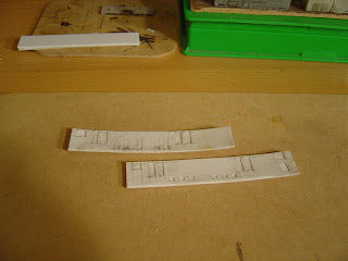
Further to my previous posts on making side details from paper, here are some pictures of the bits involved. The grill door overlays are about 1mm round the outside, but still strong enough to be cut if you have a good eye. The rest of the doors and frames are easy by comparison.


In the second photo here are the 4 sides with their base coat on ready to be assembled onto the sideframes. the paint brings out the detail much better, and while it might be a bit overdone its what the eye expects to see on the model.


And why have I painted the sides red oxide? All will be reveals in a future installment

Tuesday, July 07, 2009

Trying something old

Back to the Ed project tonight. I had a go a while back making the sides from plasticard. this involved a 1mm thick side with a 0.25mm laminate over the tip. after a couple of hour's work everything looked OK, and so I toddled of to bed. The next morning I was greeted with this vision.

"Merde"

After merrily demonstrating my command of swear words in a variety of languages I then promptly got disheartened and gave up on it for a couple of weeks.

Then suddenly the coin dropped (or a WFT moment if you will). Darryl has only been using paper cutouts on plasticard since before the dawn of the Internet, so maybe that would be better. I copied the plan that I had (remember folks, its an Addington built side with Hutt headlights) several times and then set to work. First up I scored some lines in the 1mm plasticard where the grills would be under the paper. Next I cut out the side from the plan, and after removing the windows and grill holes, attached it with 5 minute araldite.
The vent doors in the side were next, with their holes in the middle and the paneling outside the grills. The framing is about 1mm but still easy to do if you are careful (and if you rip it, it's just a paper plan, toss it and grab another). Everything is glued together with PVA.


I should have tried this years ago.

Next up was the fabled other side, only existing in photo's. As I previously recounted, I drew up the side in a larger scale and then reduced it on a photocopier.

Assuming the glue holds, I think it will work.

(You all should have noticed that I have tidied the workbench. One of the Joys of renting is the 3 monthly inspection, and I think the piles of debris that generally cover the floor in this room would be frowned upon buy the landlords. Still, at least the place gets a good clean every 3 months)

Saturday, June 20, 2009

Of Ed's again

I have not done much on this project for a while, but this week I had a crack at the underframes. The sideframes were cut to shape from 1mm plasticard, and glued to the 0.5mm thick footplate (I've neglected to add cutouts in the frame, I'll probably just paint these on in black later as it will be easier than cutting the holes, and I'm not sure i can get them all square). The footplate is supposed to be an I beam shape but this just seemed to be too much trouble for something I would hardly notice. After the headstocks were glued on as well, a hole was cut for the mech to fit in. So filing of the metal chassis was required for everything to fit between the sideframes. I then added some plasticard shapes to the ends so that the footplate would sit at the right height.


Its looking good so far. Next step is to add the journals and bearings on the outside (the real thing has an asymmetric wheelbase but I'm going to do mine with the bearings at the same wheelbase as the wheels otherwise its going to look funny), and add the sandboxes. Theres not much else to them.

Sunday, May 10, 2009

Sunday cruising

Just a wee bit done today. I added some plasticard side rails to the bogies, and also the brake rodding. I'm a bit worried about this attention to detail. Its a habit I must try to break at some point.


So thats the mechanisms basically finished. I now have to get hold of some thick plasticard to start the tops, as I'm planning to start with the roof and work my way down.

Saturday, May 09, 2009

Saturday workbench

(I often wonder if there should be a bit more organization here on the blog with specific features turning up on regular days of the week. Or does everyone prefer the organized chaos that we tend to have?)

Finally the lady of the house has returned the digital camera, so the Ed project can officially start. Heres a picture of the Kato 2-8-2 mech that will be our starting point.

The first job was to add the bogie's at each end.

The pony truck was quite simple with the main bar made from brass and a piece of brass tube soldered to the end at the correct distance. I made up a jig so that I could solder the 2 pieces reasonably square which was helped by putting the axle in position (if you have a longer piece here, it makes it more obvious to the naked eye if its square or not).


I also added some brass on top to add weight, and then some shotgun pellets (number 4 shot I think) to the bottom. Wheels are the Markits 6.2mm 8 spoke wheels with the axles filed down to stubs.


The bogie was a bit more involved. First up I soldered the brass tube bearings to each end of the brass bar (with predrilled center pivot hole) as before. I then had to make the coupling to the main body out of plastic as otherwise it would short across the split frame. I used the M2 nuts and bolts ( cheap from Dick Smith) to attach the 2 pieces together. I had to file the bolt down so that it wouldn't rub on the frame, and also the end off so that it wouldn't hit things on the track. The bolt and nut were finally secured with some araldite. Lead shot was added underneath for weight.


Moving to the frame I needed to remove about 2mm from the funny shaped bit at the end. Ah-ha I thought, a job for this new fangled Dremel type thingy. I found a grinding implement, inserted it into the chuck and turned it on. Once the shock had worn off I turned it off to find that spanish steel is not what it used to be. I'm starting to wonder if Dremel translated into Spanish really is 'spinning engine of death'. It never ceases to amaze me with its homicidal tendencies

"Maybe I can use it round corners..."

The job was then performed to old fashioned way with a file and elbow grease.

The 2 assemblies were attached to the mech at the correct points and the whole thing test run on my crap test track, where it negotiated my 15” radius curve happily. I was quite surprised that its worked, and I don't need to make any modifications to the build for the second one.


"Did I say it still is butt ugly?"