DB pointedly comments:
Studholme got moved from the garage into the basement yesterday, and this was quite easy, even with the legs extended, because each module is really light.
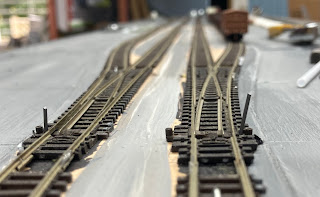
One of the last remaining tasks to be done on the 'northern end' before the fun can start, is sorting out the three 'mainline' turnouts. As discussed in a previous episode, the odds and sods points in the yard are as-is Peco points, sometimes operated with manual-remote pushrods, some just with your fingers.
But in an attempt to make the mainline ones more reliable, I have DCC-friendlied them. This is a bit of a misnomer, as they will still make DCC freak out if you travel too far off a siding into a set that aren't set for you, but it prevents metal wheels shorting out between the main outside rails, the closure rails, switch blades and frogs that might be at different polarities. It also ensures there is a really positive feed of power into the frog, whereas with the standard Peco setup, this depends on the point blades being clean and making good contact with the outer rails. Sometimes that cleanliness can be upset by ballast and glue, and dust and general gunge. Whatever that is.
This process can be done several ways, but I :
1. Cut the inner rails to isolate the frog from the points blades.
2. Linked the 'points' ends of these to the adjacent main outer rails (so the points blades will always have the same polarity as the outers next to them)
3. Feed the frog (and the frog-end of the inner rails) with the appropriate polarity depending on whether the turnout is set for 'normal' straight-on running or 'reverse' for the curved track.
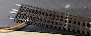
Cutting the rails was done using a jewellers saw (incredible things.... I got mine from the same place King Druff did many years earlier). Wiring was done with what looks like a blowtorch. This was actually done almost a year ago, and I've since procured a less-agricultural soldering iron, one that actually has a pointy tip! Below, plastic has been removed with a razor saw, with the joins about to be welded in:
The frog power feed comes from a SPDT switch - I bought a dozen of them from the local Jaycar and drilled them out to accept some piano wire. This way, when you move the switch, it puts the right polarity into the frog, and it also physically moves the point blades via the piano wire.
The piano wire for the first turnout was formed in a clever manner to sit alongside the ballast and under the turnout in a slot- I'm not sure if this was a good idea or not - the others are routed under the 'baseboards' and simply have a vertical bend that sticks up through the hole in the Peco throwbar.
Slots for the piano wire in place, and also for the power feed to the frog before sticking down the turnout:
You do need to enclose the piano wire into something (plastic tubing is ideal) that is attached to the layout or the wire will flex when pushed and might not move the points. And here a bit of foamboard baseboard stuck on top:
To fill in gaps where sleepers have been cut off to take rail joiners, the sleeper offcuts were cut into 'ends' and middles' ...
and badly glued in the middle and outside the rails to tidy things up, otherwise these missing sleepers can look a bit naff.
So that was the first mainline turnout done, for the next two, the pushrods were simply routed under the layout - below are two switches with their bits of piano wire which are disappearing into a plastic tube:
Ignore all the setting glue there... And below, the piano wire emerges straight up at the points end, here before the excess wire was trimmed off the top:
In between the switches and turnouts, the wire is held in plastic tube. This has a slightly unusual routing arrangement:
As I had fixed the Peco turnouts in place (because the track centrelines had to be located 'right there'), and also fixed the SPDT switches in place (because they had to be attached to the solid wooden edges of the modules), the actuating wire between them has to be just the right length to operate the points properly.
Bending the stiff wire perfectly is quite hard to do after the fact, so my wires were both slightly too long for the switch to operate the points in both positions. The solution was to 'make the wire shorter' by having it travel further, hence the little bits of glued plastic forcing the tubes down and taking up some of the slack. These little spacers of of white plastic were done with trial and error (mainly error) underneath the baseboards until the points operated nicely in both normal and reverse positions up top.


1 comment:
Try bending a kink, V, or Z into the wire at one end. This takes up excess movement, but also allows a little adjustment of length by opening or closing the V with pliers.
Post a Comment