DB follows on after a pause - this post has been in draft form, occasionally appended to, for the past six weeks.
The Studholme module build has been a bit drawn out and higglety pigglety with all manner of things occurring out of the ideal sequence. Here is an attempt to get things back into a more sensible order of operations.
Its always a good idea to paint the trackbed/scenery so if any ballast falls off there won't be white primer showing through from underneath, so this was done, as was filling in the remaining holes in the baseboard framing with foamboard.
After these pictures, the track centrelines, obliterated by that recent application of grey paint, were redrawn.
So finally things are at the state they should have been before any track was laid many months ago! Now feels like a good time to put down more track and start soldering it down across the PCB joins.
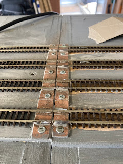
As the old bomb disposal line goes: "Cut the green wire...." Snip. "But first, cut the red wire." A clever tip I picked up from somewhere was to loosen the module joining nuts a little, then place a very thin sliver of cardboard or plastic between the modules and loosely tighten everything up before the track is soldered down and cut. Then after cutting, remove the card and tighten things up to remove the Dremel-cutting-wheel-sized gap between the rail ends left from making the track cut.
Its also quite hard to cut the track vertical because the Dremel's fat motor body is a much larger diameter than the cutting wheel. You are often left with a V shaped cut.
Fortunately, the second-hand Dremel that I have (its a Fuller one actually) came with one of those flexi shaft extenders which has a thin endpiece you hold onto, so this makes it a little easier.
I suppose a jeweller's saw could be used if you had the track up on a decent embankment or a really thin wooden module end.
You could also simply butt cut sections of track together and stick them down, but I figured with my module mounting pins providing a reliable location during module mating (ooo, err), tracks that are soldered across the join before cutting should all line up perfectly every time.
The real place had, to the east side (to the 'right' of the picture below), a main, loop, goods loop/shed road, and a loop around that goods shed that I remember being used for fresh fruit. The Froot Loop as American cereal makers might say.
On the model, I've decided to move the goods shed 'east' one track, so that gives me a main, loop, another loop, and then the goods shed. That means I'll be able to practically have four decent sized trains crossing here (including the west 'island loop')without having to run through the goods shed (which was previously, per prototype, on the long eastern goods loop) or loop around the fruit track. I've left one stub siding in to represent that fruit track, so a Z could be parked there. I doubt that this or the goods shed little loop would ever be used much in operations, but they do have reasonable large radius points for looks.
- the island loop can be used by the main DCC feed for mainline crossings, while a branchline train comes into the runaround loop.
- or the whole island loop (right down to the far end) can be used for a Waimate branch train to come in, run around and shunt (including accessing the near end of the island loop)
- or a mainline DCC goods could drop off wagons into the far tail of the island line for the Branch loco to pick up.
- or the whole thing could be run by the DCC controller so that a mainline train could shunt the coal/seed siding.


4 comments:
Good progress. Practical loop space and operations area by the looks.
Excellent progress. I still need to start on my two modules but I have a solid plan
Could you extend the seed/coal siding and add the stock pens to that ?
Could you extend the seed siding and add the stock pen to that ?
Post a Comment