Sunday, June 14, 2009

(Not so) Great Workbenches of the World: Lower Hutt

AmFet writes: After seeing the superlative workspaces belonging to the Head Druff and KiwiBonds, I thought I would amuse the pundits and present where I wile away the odd spare moments when they present themselves:


The bench itself was grabbed from an able Squadron Leader and is hinged so the front drops down for easy storage. As I dont have a permannent place to "spread out", I need to be able to setup and take down at the end of every session, hence the reason why the bench is looking so tidy! In the pic above, the bench is setup for soldering operations with the hand-built lowmelt setup featuring upstage left.

Pointing the way

Well, I finally got over my fear of making trackwork this week. I had made a short stretch of straight track, but if I was going to get anywhere I had to be able to make a point. Woodsworks provided the template for an NZR No 7 point, and so I was off (well, it sounds easy but actually getting the gumption up to actually start took some time). As this was to be a test piece I just went ahead and had a crack to see where the pitfalls were.

First up I glued the plan down onto a piece of MDF. The PCB sleepers were then glued down with a glue stick so that I could remove them at the end. The outer rails had areas filed into them where the point blades would sit in them. then soldered down the outer rails, using an old track gauge given to me by John Rappard 20 odd years ago. I assume its about right. I then filed up the crossing point bit (sorry, can't remember its name) and using the track guages installed it about the right spot. the wing rails were next to go in. I bent these up and then positioned them, discovering in the process that 2 pieces of code 55 rail soldered side by side give a surprisingly good gap that even the Peco 'cookie cutter' wheelsets will pass through. Yah number one here.

'don't look at the solder'

Next up was the point blades themselves. These have to be filed quite thin so that they will bend and fit into the rail notches at the head end of the point. I didn't have anything to make a tie bar out of so I've left this.


For a first up effort I've found that there's some things that worked, and some bits I need to do better. I do need an NMRA track guage, and some jigs to solder up several bits. Apart from that I think it's the way I will go on the new layout.

Saturday, June 13, 2009

Saturday morning comments

Well, I've finally woken up, had the first hot chocolate of the day (I hate coffee and vast amounts of tea are not good for me either) and just checked though the comments to see what's been going on while I was in the land of nod. And I see everyones been playing while I've been asleep.

The 'lets build a loco kit' discussion rolls around every 6 months or so. It quickly splits into 2 camps and then fades into the distance again (I've written about this before here).

I'm not sure if going with the Bullant is the right way though. $240 for the mech before you do anything else is a lot of cash. Add in $150 for the top etc and thats basically $400, which is more than you would pay for an S scale kit. At that price demnad for the model could/would be very close to a round number (how many people WOULD pay $400 for a De or an Ab KIT). I could be corrected but I think most of the modelers in the scale operate on far lower budgets than that. Rumour has it that North Yard doesn't make wheels in 120 becoause 'theres no big market for it' and he is most probably right.

I think any loco kit thats going to come about will be due to some kind soul who wants to sink his money into a project and lose some of it to get a model he really wants. Anything else may just lead to getting burnt.
(well, thats my opinion, but you are all welcome to toss in your own.)

Friday, June 12, 2009

La-Z-Boy: RFL and Speights containers

DB says: I think I can reclaim my Laziest NZ120 Modeler title. Sn3.5 modeler Darryl Palmer sent me two pictures overnight of a couple of wee gems on my wish list.


Pics courtesy Darryl Palmer

I adjusted the RFL picture's perspective in Photoshop, cleaned it up and eventually managed to get a complete copy out of the printer. Yes, the entire side of my wagon - door, hinges, rain gutter, rubbing strip and all, is a white backed decal. Lazy bugger.

If you'd like to make your own, I've included a file at the bottom of this post, so don't say you don't never get nothing from the Dandruff Brothers. Print it out on a laser or photo printer, stick it on a plasticard box and you'll be laughing. (at it).

RFLs ran in both Islands from 1980 through 2008, albeit now rebuilt with treble doors and alas they lost their signwriting in the late 1990s, by which time the former-UK wagon and the container were jointly considered a "VRA" wagon. Presumably they ran around with TranzLink branding until recently. Our contacts at KiwiRail seem to think these haven't run in a few months, so it may be all over red rover. There are plans in the August 99 Journal that (as usual) surfaced right after I built it - just in time to point out my mistakes!

I found the Speights logo in a dark corner of the interweb and printed it out on the same sheet. By the time you read this, the horrible blue GSX box container will hopefully have been made more presentable.


So now I have a beer container to go with my wine ones. Shame they never made cider containers, or Blenheimer Cask box containers with little plastic taps on the ends. Time for a beer methinks.

RFL jpeg file provided for your pleasure.
Hope the blog didn't down-res this too much...

Thursday, June 11, 2009

It had to happen

I see there's been yet another enquiry about a De model in the comments on Darryl's DFT build. For those of you not on the yahoo group this has been cropping up since 2005, when someone was busy collecting drawings and was just doing the masters. Now personally I can't see the fascination with the loco; the photo's in the Railfan articles showed a loco that was not overly pretty from some angles and only really worked as a shunter. I'll admit it did look nice in the fruit salad scheme.

The main problem with building a model of a De is that there is no powered bogie I'm aware of that is remotely close. If anyone knows of anything usable ( The Minitrix H12-44 and the Farish class 20 are wrong sorry) the following criteria need to be met; bogie wheelbase of 20mm, and a bogie pivot spacing of 41mm (this one is negotiable).

Finally (again) we have the normal question; So whats everyone else doing. send us some pictures and we'll publish them, if only to give Darryl a break from slaving away at the modeling bench so he can enjoy the Long Island summer.

UPDATE; doing a bit of searching last night, and it seems to my Mk1 eyeball that the Dapol Hymek might have the right bogie wheelbase for donation. I'd like some confirmation though about either the models bogie wheelbase or the real things bogie wheelbase.

Kettle time

Another new project tonight here at Chateau Dandruff. Why finish anything when you can start something exciting and new. I made a trade with another modeler to move one of my 4-8-2's which I was not happy with (don't get me wrong, its a very nice bit of kit, but to my MK1 eyeball the wheels are just too small; a fact backed by my plastic Chinese calipers). The replacement is this lovely Dapol 4MT 2-6-2.


The immediate possibility that springs to mind with that beautifully made valve gear is a Wf. Looking at the NZMRG plan the immediate observations are that the wheels are a bit big and the wheel spacing is 1mm too large, the cylinders are a bit on the small side and too high, and the trailing truck needs to be replaced with a 2 axle bogie. The driving wheels I can't do that much about, but the rest...

First up remove the top. The screws are under the trailing truck and in the chimney of all places. The plastic top is then removed for future sale to some simple minded English outline modeler on trademe. Carefully break the glue bonds that hold the cylinders on and then remove them by moving them forward and up. Take care of the waggly bits as they are made either from some really soft reject Chinese steel or toothpaste tubes; easy to bend, but just as easy to bend back. To lower the cylinders you will need to remove about 1.5mm of plastic from the marked area. Carefully remove the plastic by filing until the center line of the cylinder lines up approximately with the center of the driving wheels. At this point I also cut all the detail off the front of the cylinders.


The cylinders are then carefully repositioned and all the waggly bits lined up again. its times like this you wonder why god didn't give us more arms and hands to do jobs like this as you always need a spare pair of tweezers to move something else into position. I just did it sober...


A very minor detail is that the upper link on the valve gear should be flat. I did this by removing a plastic pip at the front of the valve hanger and gluing the link in a level position.


The next job is to remove some of the metal from the motor holder in order to fit the boiler underneath. I'm not sure if its needed yet but best to do it now while the beast is in bits. You can see from the picture its possible to remove quite a bit of metal without breaking anything.


Final picture is everything back together. Next step will be the construction of the rear bogie and fitting it into position, accompanied by the removal of a fair bit of metal.

Wednesday, June 10, 2009

Diesel in a day (or three): DFT part 5

I ended my second afternoon of DFTing by painting her up blue, yellow, gray and black, and now that the paint is dry, its now time to wrap things up by documenting the third visit to the trainroom.
Going back to that epic post on colour, I began the session by dulling down my deep sky blue and dark gray with a wash of rapid-drying light gray acrylic which has made it look a bit more like the real 7132 trailing in this shot from a few months ago (which has just this week become my inspiration for this model).
I absolutely loathe doing handrails, but once they're done they make everything look more finished. I used very fine brass wire this time instead of my usual piano wire and the superthin ones look waaaaay better. The light attached to my workbench (the black thing in Ev's workbench post) has a (scratched) plastic magnifier built in that has never been used until painting those handrails. Boy does it make that job so much easier. My eyes must finally catching up the rest of me.
Tranz Rail's flashy decals were from the superb Etchcetera (Andrew Wells) DC set - the cab numbers aren't the right font for the blue livery, but they will do for now. I gave the loco that ugly 'patch job' look with one more wash of the gray paint in an approximate rectangle. For some reason, many of the DFTs got a much lighter patch than their underlying blue paint. I might cover some of these 'finishing' steps in more detail in future models/blog posts because I forgot to take pictures and I'm sure you're getting sick of DFT tops by now.

Finally, a Kato SD40-2 chassis for it to sit on: I pruned the shock absorbers and some of the 'underbrake' bits off the bogies and made battery box sides from strene. The -2 fuel tank was simply shortened to save time as the end profiles are similar.

And that’s that!
Having not seen a lot of real DFTs in action, I must confess to not being a huge fan of them ...last week. This project started out more as something that would be 'good for the blog' rather than a loco I just had to make, but once the thing started to come together, I started to enjoy that feeling of making something from scratch and am now quite in love with a model which turned out really well.
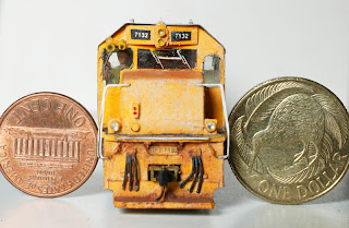
Dangerously close. Ditch lights in, but needs headlights.
Having said that, if you are going to have a go at scratchbuilding for the very first time, I'll warn that the DFT is a more difficult model than I'd thought. There's all the lumps and bumps, the underframe stuff, the painting of the raised walkways and yellow stripe - that make it quite a bit more tricky than doing, say a DC, which would be a more straightforward scratchbuilding project.

And -before I forget - something I forgot to do on this DFT, was to make the whole top about a mm shorter than it should be as I did with my DFs. This would have tightened up the gap between the rear bogies and the back end a smidge, although looking at the pics above it doesn't look too bad.
Scratch That
I started this project with the comment “Before you ask, it’s not going to be cast, RP’d or etched. Instead, it will be quick to make, cost next to nothing and require almost no skill.”
That wasn’t intended to be a swipe at the technologies that will turn NZ120 upside down in a few years. But... isn’t that what everyone said ten years ago? I'll reiterate from a few months back: manufacturers rarely produce products for love, the market is tiny and bringing products to that market is an incredibly time consuming and expensive proposition. You do the maths.

My point is this: you can wait for things to drop into your lap, but you can also make something out of nothing today, and get a great feeling of accomplishment from doing it. Surprise yourself and then surprise someone else with it and perhaps get them interested in the scale. Given the usual 2-3 foot viewing distance, there’s no better scale than NZ120 for scratchbuilding stuff; which is a good job given the incredible number of fancy kitsets and RTR items available.

So get of that armchair, bring that beer with you and have a go. After all, this DFT top isn’t too bad for a ten dollar, paper-and-plastic, two and a half day effort eh? As Bruce Forsyth used to say : “Hope you’re all doing this at ‘ome!”