Wednesday, April 07, 2010

"But it works in the bigger scales..."

Am_Fet writes:

Back in the days before iPhones and iPads, I modelled in Sn3½. Not very successfully, mind you, but I still enjoyed it....and after all, isnt that what a hobby is all about?

One thing I have always been taken with has been the "Finescale in Small Spaces" ideas as championed by one of my real heroes in the model railway sphere, Iain Rice (The fact that I was unable to meet him in Chch was a bit of a blow). I always thought it was something that I could have a go at, and did, using a track plan from another luminary, Neil Rushby. The layout itself (called "Shell Island") was simplicity personified:


I immediatly started designing my own, and "Teschemakers" was born. Based on photos I have of the last days of the Waihao Downs branch, it celebrates dereliction and decay as much as it does unkempt roadbed and weeds.


I even got as far as mocking up the beast on some customwood in the bedroom one evening, with guild plans of the Rata goods shed, a stock yard and a rail crane added....and a red plastic tumbler thrown in to represent an old lime kiln:


And building the base for it....


And then...Catastrophe! The contractors discoverd Nz120, and the entire kit and kaboodle was consigned to the outside shed, only to be found infrequently while searching for other things.

However, recently I've been wondering if I should start again, but this time in Nz120? I still like the concept, and with the nucleus of a nice Dj hiding over at Druff HQ, the J wagons for the sheep yards well and truly shot and the feeling that a good shed and sheep yard would be "achievable", it might be time to break out the foam board and have another crack, creating (in effect) "Teschemakers Reborn"...


Simple and quick...might be just the ticket, really...

Tuesday, April 06, 2010

Gorgeous. A new layout section for DB

DB: Ornathologises:
It's springing spring here so there's just no time to be playing trains, but sometimes one needs to escape from a crazy work-riddled life (with cleaning up the garden thrown in for good measure) and take a breather to pray at the NZ120 alter. Time for me to make another module/section as I blaze a trail - slashing my way through bush, mountain and stream - to pioneer the highline around my geographically challenging trainroom. You can see the general idea for the module above, and more clearly below, with the trackbase cut out to approximate the curves that happened to be in some soldered flextrack that I salvaged from the previous layout. The curve in the distance will plug onto the left end of Moana.
As you can see, the thought is to have a bit of cliffside running to make iteasier to see the trains from below. Lastly in the pic below, we can see construction beginning on the backscene (lying flat in the picture). The backscene will go 'up' in the normal way, but will also extend 'down' below track level to provide additional rigidity.The little ribs have been stuck on to the backscene at appropriate places so that I will be able to plop these onto the trackbase and glue the thing in place without the backscene slipping down while the glue sets. That might become clearer in the next instalment. .

Pictures taken with my crappy cellphone camera. I won't be covering that in the next photography post...

Monday, April 05, 2010

Doing the Business...

Definition:

"Business cards are cards bearing business information about a company or individual. They are shared during formal introductions as a convenience and a memory aid. A business card typically includes the giver's name, company affiliation (usually with a logo) and contact information such as street addresses, telephone number(s), fax number, e-mail addresses and website. It can also include telex, bank account, tax code. Traditionally many cards were simple black text on white stock; today a professional business card will sometimes include one or more aspects of striking visual design."

Am_Fet writes:

Okay, so this idea came through a wee bit late to get to the convention, but I was throwing around the idea in my mind of whether to give Cabbage some business cards to hand around at the convention this easter weekend.

One of the more effective business cards that I had seen came from Fiddlers Green, a card modelling website. In a nutshell, their business card came with a complete J3 Cub that you could cut out and assemble...good stuff!

So....would such a dodge work with us? I quickly scribbled off an L4 top on the standard business card size in 0.4mm ply and sent it around the MD hierachy for comments:


The Head Druff himself replied:

"I think its a good one. Its a pity that you can’t do it for modern wagons. So an L1, L2a, M, a workmans hutt, a Jigger? If the underframe thing comes off then a Q. A K box wagon (no roof). In fact anything that would take up a card space (wee lineside buildings etc). Very much along the lines of the old BM model, so don’t have to be perfect (no roofs general outline correct). Maybe charge $5 a piece"

So what do the Peanut Gallery think? I dont think there would have been many left if I had got them done!

Sunday, April 04, 2010

Earthing Google...

Again, Am_Fet writes:

Well, again it looks like I will be carrying the hopes and dreams of this blog, unless Kiwibonds can get some time of from trying to take over the world (or at least large chunks of it). The Head Druff and his good wife passed through for lunch today, picking up a J5 and confirming the mystery guest photographed this week.....and to say I was envious......

Anyway, onto todays post: Actually using Google Earth for something...well, useful really. My planned Patea layout will feature the old Cheese Store complex as its view block on the right hand end. Its a massive collection of crumbling, decaying old buildings....and its gorgeous. But how to work out how big this sucker was going to be?


Thanks to the genius inherent in the design of Google Earth, it actually wasnt too bad. The first thing was to actually find the cheese store and zoom in on it. Level of Difficulty? about 0.00001.


Next, select "Show Ruler" from across the top toolbar:


Now, just click between two points on your building and read off the distance (you may have to set it to kilometres). Sure, you will need to do some conversion to the correct units, but its metric....no hassles. As you can see, the complex here (including wharf) worked out to around 120 metres.


Now for the calculations. True to scale, the complex would be a metre long (thats 120m / 120 = 1.) Now, I never build things true scale unless I've got an aircraft hangar to put things, but I've settled on only foreshortening items by a third. So, a third of a metre is 660mm. From here , I can load the image into Autocad, scale it to 660mm long, then run dimensions off it to suit. (in fact, on this one I went a bit bigger to retain the length, plus I designed the layout to be able to accept it like that).


Dont think you need AutoCAD to achieve such trickery either. It can also be done with a drawing board, a ruler, calculator and some clear logical thinking (i.e not after a few glasses of alcoholic punch!)

Saturday, April 03, 2010

Rail Weigh Station

A Convention avoiding Am_Fet writes:

Here is a little something I've been working on for my day job. Admittedly I havent been doing much (all back end IT stuff with servers, databases and the like) but its still good to get involved with something that actually matters, rather than trying to work out why the finance department cant print anything....

This is the new CIMW System (Computerised In Motion Weighbridge...I think). There are two of these being installed, one at Rolleston and the other at Bunnythorpe. Last Tuesday I flogged the company Camry and went up for a look.


This is the Bunnythorpe site looking back towards Palmerston Nth. The main shed contains all the processing and communication gubbins (wireless via Vodafone) with trunking runs leading to the components mounted either side of the track


These wee yellow bits are the actual weighing components themselves...its got something to do with measuring the downward stress exerted on the rail as the train goes past and then factoring in the speed blah blah blah...I'm sure there are long magazine articles in learned journals that explain it all. The only bit I get is when the engineers say "Hey! It works!"


A couple of items in this photo; the silver channel thing (with attendant "other bit" mounted on the sleeper inside the rails) is actually one of two light beams that calculate the speed of the train as it passes. The two square plates mounted on the pole behind are RFID tag readers that pick up the information from tags mounted on the wagons. The tags themselves will only hold a serial number; all data will be matched in the backend database server, meaning the tags themselves dont need to be so brainy and can be easily replaced.


Finally, two of these cabinets sit either side of the line. They are RailBAM sensors, which I have taken to mean they are acoustic devices that listen for the sound of knackered bearings. As the sign on the front says, "Shutter May Move Without Warning", which leads me to believe they swing open to allow the hearing devices access to the open air.

In the event of an overweight wagon or knackered bearing being detected, an alert will flash back down at Train Control in Wellington alerted the TCO that there is an issue. He can then interrogate the error and be able to ascertain which wagon(s) are at fault and take appropriate measures. Also, an automated message will be broadcast on Channel 1 (Local) informing the driver of the issue.

I suppose that working on this site got me thinking about the "You never finish a layout" adage. This piece of detail could quite happily consume the odd evenings building time...and for those with operational aspirations, you could even work it into the Operational Procedures that sometimes it goes off and wagons will need to be dropped, or the speed of the train reduced.

Finally, it seems the Australian guys installing the system cant get over the complete lack of security around railways in this country.....and its true. This installation is out in the middle of nowhere with no security at all....how long until some nutbar works it over??

Friday, April 02, 2010

Taking the plunge

Today is the start of a new adventure for me...into the practical realms of hand laid track. One can talk all one wants, but its now time to put up or go home (or something like that, I'm working at home, maybe I should just go to another room or something. Whatever)

The method for building track like this was developed by Graham Venning. It's main premise is to make the plan dictate the track layout, not the track dictate the yard layout, which is what you get using ready made track( also to some extent the track made using commercial templates). It takes a bit longer to do, but the end results are beautiful flowing trackwork just like the prototype (mostly. Don't tell me, I know some bits are pre-made).

The first bit of track that I am building is the electric loco siding on the southeast side of the station.

To start with, the track template for the particular point formation is laid out on tracing paper from the full scale version I drew earlier. This is then taped or pinned to a board. The first step is to mark out where the sleepers will go. I am using a sleeper spacing of 6mm (which is about 1/2 way between the 5mm-6.5mm of the prototype) which makes the maths much simpler. The first job is to measure the spot where the 2 diverging tracks are 9mm apart, draw a dotted line, and then measure 1mm behind this. The dotted line is the approximate position of the point of the frog. Mark out the position of the sleepers in this area starting 1mm behind the dotted line with 3 sleepers both sides of this first sleeper. Draw a line 9mm either side of the track center line. This will determine how long the sleepers are (Yes, I know that NZR uses sleepers in standard 1' lengths, but I didn't have much of the longer sleepering to go round, and its going to be completely buried under the ballast in the yard). Next mark out where the 2 curves (or curve and straight) intersect, and mark this. Draw another line 1mm back from this and place a sleeper plus one 6mm further away. The intersect mark is where the point blade will end, and the throwbar goes between the 2 sleepers. Next mark out 2 sleepers 30mm and 60mm from the second sleeper. They will will hold the track in position through the point throat.

Then mark in the rest of the sleeper positions every 30mm (every 5th sleeper).
This shows what it looks like when all the sleeper positions are marked.

As you can see have also marked in the line 9mm off the center line. This is where the end of the sleeper will sit (Woodworks supplies 18mm long sleepers which scale out to 7'). the sleepers can be stuck down with either paper gum or double sided selotape. Here I've used option B.

Stick down all the normal length sleepers.


I then took some longer sleepering and measured it in situ. This was cut in a vice with a fret saw.

'Whoops, wrong hand!'

These pieces are then stuck on one at a time. My friend marks the sleeper with its length so as not to be confused, but I have just labeled them from 1 (since there is not that much space to write on the sleeper).

Once you have stuck all these in position, you are ready to start cutting and soldering track.

However, since its Easter (and these posts are pre-written) I am currently sailing the high seas back to Wellington, this will have to wait till next week when I get back.
(I also discovered while moving it tonight that the MDF board I used as the base is warped. Feckity feck feck. I'll have to find something else.)

Thursday, April 01, 2010

NZ120 Photography part II


DB follows up to this first piccytaking post, since he isn't doing a lot of modeling at the moment:

Macro

I had a query or two about 'macro' settings on a camera. The term in the old days referred to close-up photography - specifically being able to magnify the subject such that the image recorded on film was close to the size of the subject itself. There are many techniques that can be used but the most common these days is the 'macro' setting on your point and shoot cameras or on lenses - both of these allow you to focus on something really, really, really close to the camera.

There are three things to bear in mind when you get up really, really, really close and personal to your models (four if you count that all its flaws will be magnified!)

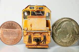
Firstly, you will recall from the previous discussion on depth of field that the closer you get to the subject, the distance in focus fore and aft of it will be greatly diminished. When you are really (really, really) close, you need the smallest aperture hole (biggest f-number on the lens or camera settings) you can get to keep this distance as deep as you can. Luckily, in the above pic, only a small depth of field is needed (from the coupler to the cab face). In fact up that close, there may not have been much more DOF on offer, even with the lens closed down to f32.

Secondly, the small aperture means you have a longish shutter speed, and this, coupled with the 'macro' effect magnifying your camera-shake, might lead you to consider sitting your camera on a tripod (or a book or something else solid). And possibly a cable release as well to stop you moving the camera as you push the shutter. The poor man's cable release - which you can use for night shots of real trains as well - is to use the self timer to fire the shot. This gives a few seconds for the camera to stop wobbling (even on tripods a camera can sometimes move a little) before the shutter fires.

Thirdly, if you are really close to your subject, a camera flash may blow out everything up close into a nice shade of glaring white, or then again, it might shoot right over the subject, or you may have nasty shadow problems. See that previous post for some diffused lighting ideas.

Going Wide

Zooming in using a telephoto lens often creates drama in train photography, but this rarely works so well in model space because you lose precious depth of field with tele lenses as we saw in the last edition.

We also saw that wide angle lenses have the opposite effect, and that bonus DOF holds in model pictures as well, so more of your shot will be nice and sharp. It also gives a 'different' view from the normal 50mm lens look that you usually see in model pictures.

Getting Low

Getting down low, close to - or even sitting your camera on - the tracks or scenery also produces 'different' and more appealing pictures than those taken from up in the sky by the Camera of God. Be careful to shoot around foreground items/trees that would be out of focus.

Advanced Class: Extending depth of field by combining multiple images
Although the small-aperture trick will keep most of your regular model shots acceptably sharp, it won't if you need things to be in focus right up close to the lens and also a metre or two away.

Something you can try in that situation is to take a few pictures each with different distances in focus and then blend the bits that are sharp from each picture in Photoshop or a specialist focus-stacking program like Helicon.

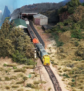
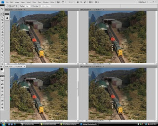
The picture at the top of this post covers about five feet of module with a mild telephoto lens - a depth of field challenge even with the lens stopped down. So using a tripod, I took four pictures from the same spot but with a different focus point for each - foreground, loco nose (top left - note the background is a little fuzzy), middle distance and background (bottom left).
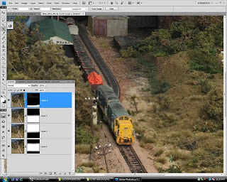
These were blended as four Photoshop 'layers' (below) where the fuzzy areas I didn't want to show in the completed picture were masked out or erased from that layer, leaving just the four charp areas to show through as the final image.

Techy Note: Colour Temperature and White Balance

In this day and age, the fact that different lighting sources give off different colours isn't such a problem. It was with film (anyone remember that film stuff?), of which most types usually expect light from our friend Mr Sun. If you took a shot with film inside an office (without a flash), the fluorescent lights made things look greeny. Inside a home lit by those old illegal incandescent light, things looks yellowy/orangy. Light from camera flashes is usually quite blue. Etc Etc.

Modern digital cameras try to deal with that using a 'white balance' sensor, which adjusts the colour balance to make all the pictures look 'daylighty' - which is what we're used to seeing in pictures. Usually this works fairly well, even with mixed lighting. When taking model pictures, I usually have an incandescent light on so I can see what I'm doing, but I use a flash for the main or fill lighting. But you wouldn't know that because the camera corrects for it.

For film cameras loaded with daylight balanced film, you need to put filters on the lens (or the light source) in the inverse of the light temperature. For example a yellow filter takes the blueness out of a camera flash.

The only time this is a problem for us is if we mix light sources in different areas of a picture. For example a layout is lit in the background by a strong incandescent light and a flash is used on part of the foreground. That could be fixed by putting a see-through yellow plastic 'gel' over the flash or more trickily fixed in Photoshop.

I'm not sure that even I understand what I just wrote there...