Friday, June 28, 2024

Only CE CEs are tasting like theees!

DB recalls somewhat verbosely:

A long time ago, in a galaxy far, far away, I purchased four well-travelled CE tops from Shapeways - in 2013.

They were unpacked recently and I thought they might make for yet another quick project that will keep me away from finishing that last leg and thus progressing Studholme.

Some hopper history. On the Midland Line coal trains, the aluminium CB wagons started to replace four wheeled highsiders in 1989. CBs were a derivation of the North Island CA class but with longitudinal doors underneath as it was feared the wet west coast coal would get stuck in the little transverse doors.

Extra CBs were converted from CF fertiliser wagons as coal tonnages picked up, and hungry boards were added to the tops of all of them to further increase capacity.

The stainless steel CC class arrived on the scene in the mid 1990s, a taller and longer wagon intended to be loaded with considerably more coal as soon as the Midland Line's track and bridges were upgraded to take higher axle loads. That never happened, so the one-bay-shorter CEs came about, and CCs still run around with plywood formers inside the ends to prevent them from being overloaded. 

As the CEs were entering service, some second hand bauxite tubs from Western Australia were purchased, and these became the CW class with their distinctive lower sides. They initially ran as a set, but then they were split up so for a period it was not uncommon to have real mixtures of wagons in the west coast coal trains, with a block of modern  CE/CC wagons at the east end, a block of CBs in the middle and some CWs at the west end (from memory to do with braking when loaded, although I do have pictures with some CWs at the east end of trains).

The bigger CE/CE wagons are labeled for unidirectional unloading, and now there is no balloon loop at Lyttelton, I guess they shuffle out and back to Ngakawau, Reefton, Ikamatua (Pike River) and (rarely) to Rapahoe with little bother. They'd have to be careful at  Stillwater to leave from the same leg of the triangle they came in on to avoid reversing the rake. 

The Genesis CET wagons used to bring coal to the Waikato from the Bay of Plenty ports are basically CEs with roof hatches, and the YJ ballast wagons were derived from the CE design. 

Anyway, back to the models. 

As mentioned in that post from 11 years ago, the shells from Mr Lister are fairly strata free except on the sloped ends. I attacked that with a triangular file to take some of the edge off, I'll give myself a C- grade on that effort. The sides were sanded with some fine sandpaper, but now that I have applied some paint they seem as gritty looking as ever. 


The only 'modifications' made to the shells were to shave off a mm or so from the bogie mounting point to make the wagons sit lower on Microtrains bogies, and to enlarge the coupler openings for the bogie-mounted couplers to swing around in. Both done with a drum sander in the dremel. The material these were made off seems to slowly abrade and melt away rather than turn to dust like the 3foot6 resin. The underfloor longitudinal stiffeners connecting the bogie mounting blobs to the main wagon were also shaved slightly on their longitudinal edges to allow more swivel for the bogies without flanges contacting them.
Somewhat silli-ly, paint was applied next. Spray primer, followed with some silvery Tamiya paint which I planned to weather with black paint for coal dust.
The CEs looked shiny when new, but quickly acquired that dark sheen or course. This was applied to most of the wagon (especially the bottom half) with dark grey paint wash, but went too far trying to blend it and covered almost all the silver. Having me wonder why I applied it in the first place. The dark wash looks ok in places and pretty bad in others.
Certainly 'sheen' isn't what I'm getting with my efforts so far thanks to the un-smooth surface of the prints. However, a day later I gently resanded the top halves of the shells with some very fine sandpaper and this not only smoothed out more grit, it removed some of the crappy dark wash and brought more of a shine to the top corners.


Now that I have foolishly painted the shells, in a bass-ackwards way I figured I should detail them. D'oh.

 So after trawling through the stash for CE pictures, it seems:

  • One end platform of the wagon, the Lyttelton-facing end, is basically empty save for a set of four wooden wheel chocks. 
  • The other, west coast-facing end, has a long air tank (there seem to be different lengths or positions of these), some braking bits and bobs, and a handwheel. 
  • There are two air pipes of different sizes running along one side, these end up going down into the end platforms via metal gymnastics. I'll probably just do one pipe unless I suffer from a burst of enthusiasm.
  • There are handrails on one corner of each end. 
  • There are trippers for the doors on both sides, these always seem to face to the left when viewed from the sides. I assumed they would face one coast or the other.
  • There are some prominent jacking pads on the bodysides.
  • The model shell has a little flap at the top on one end. I have prototype pics of flap with a ladder attached to it, ladder with no flap, flap without ladder, and no flap or ladder. The flap was probably intended to protect the air tank and brake valves, so I'm thinking they started with a flap for protection, then decided they really needed ladders, then later on, decided to dispense with the flap. The wagons mainly seem to be in 'no flap with ladders' configuration these days. Perhaps someone in the know can share some actual facts.

Some representative air tanks being made (below). Jacking points and little trippers for the three door sets have been added with white styrene.:

Drilling holes in the end platforms for brass ladders (below) to minimise the chances of them being knocked off  - I decided to keep the flaps on two wagons and cut them off the other two for some variety. A brass airpipe has been painfully bent and secured in place along the correct side.

Ladders in place and handbrake wheels too (below). The handbrake supports were over engineered with an angled piece of plastic rod with a thin square attached on top, all drilled out for an N scale handwheel donated by some unloved American wagons. The angled support was shaped at the bottom to plug into a hole drilled in the end platform. This looks almost perfect on the wagon below. On the other three the angle was too great (I forgot that the platform top also slopes down at the sides) so those ones lean a bit more than they should.  

And finally with some paint on these new details (below)

The Marks Model Works etched brass CB ladders were purchased a decade ago with these four CE shells in mind .

Monday, June 03, 2024

DSJ Part 6. Handrails.

 DB teters onwards:

A few minutes were available for trainroom duty today, so some handrails sprung from the holes that were drilled last time. I had grand visions of soldering these up on the workbench nice and straight, and then inserting them into the holes. This was never going to work as I'm shite at soldering, and all my superglued ones from the ancient past are still intact. More or less, anyway.

So an overall hoop of brass was folded to fit and glued in the outer holes. Then the central vertical piece inserted into a hole, cut to size iteratively, and glued to attach to the hoop. Then the two remaining vertical pieces done similarly. 

To finish things off, the horizontal bar was glued in place (which I assumed went all the way across, but after looking at a few prototype photos, doesn't). The first horizontal bar, on the unpowered/short hood end went in nicely first pop, and the other end had to be wrangled about and a small kink added in the middle with tweezers and fingers covered in superglue. These end rail pieces were all made with leftover (0.6 or 0.4mm??) brass rod that came with the Trackgang Zs. Overall, this didn't take as long as would be imagined. 

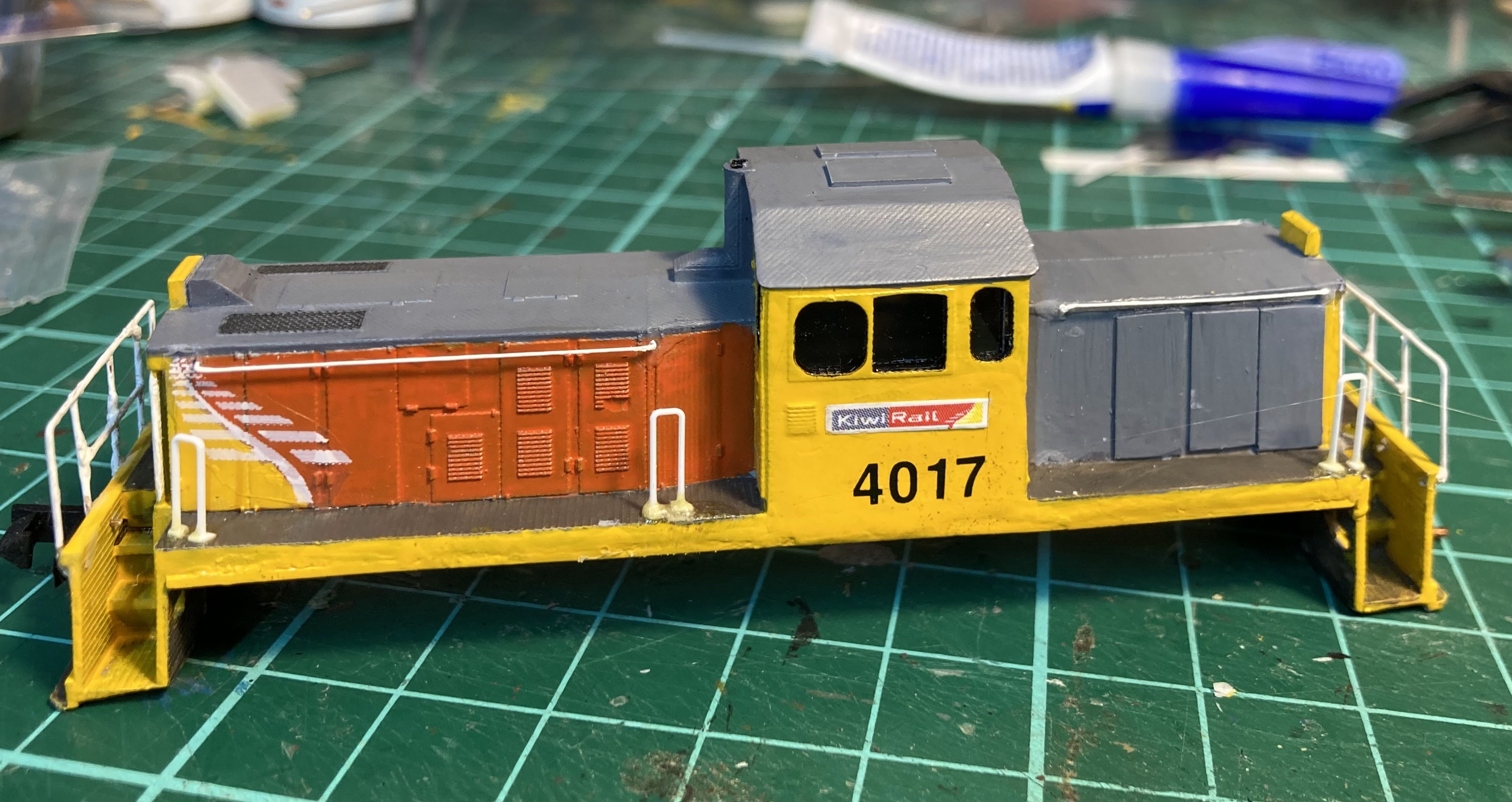
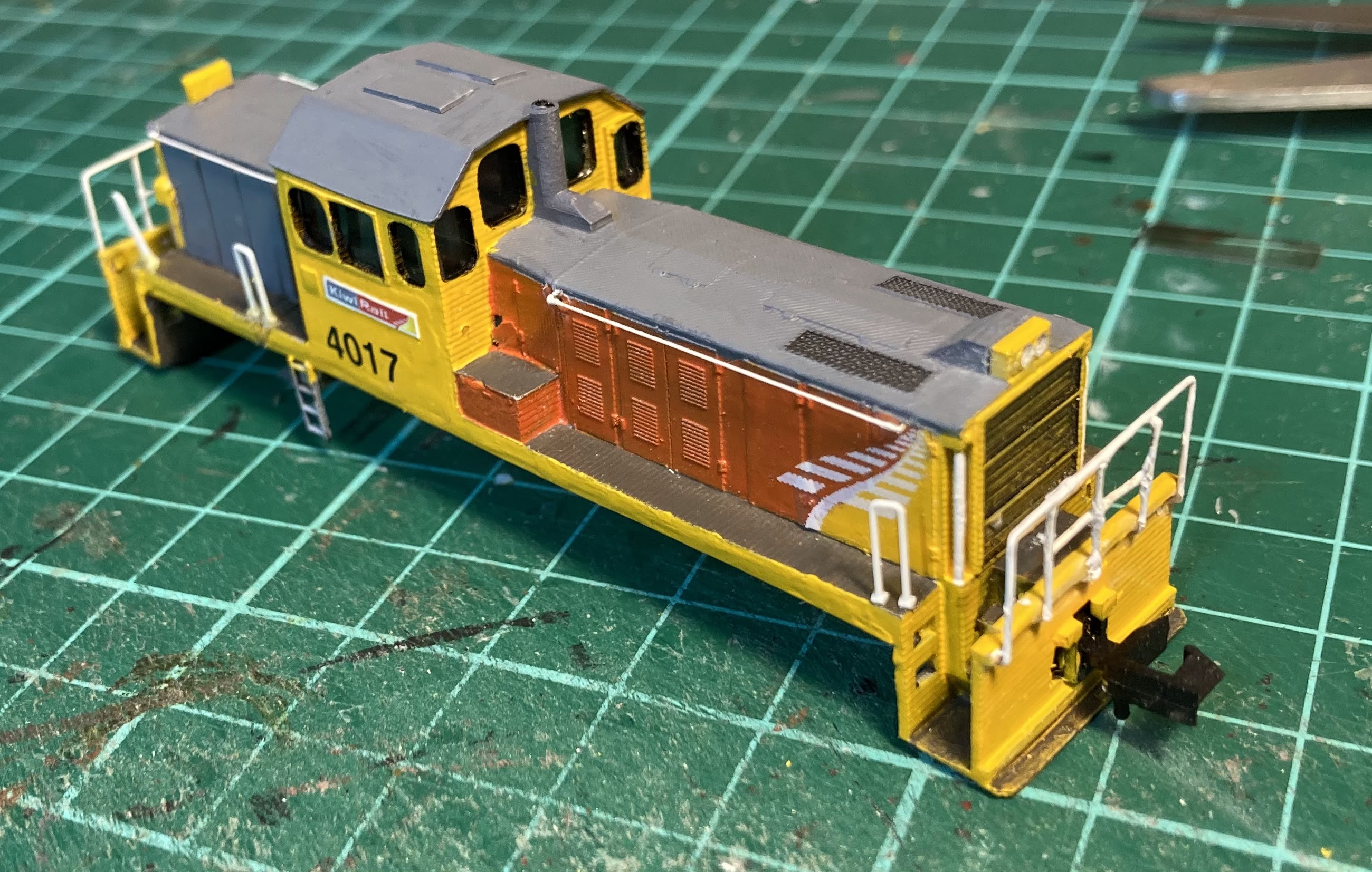
Ironically, the 'short hood' set of rails is pretty straight and square (whereas the short hood end itself isn't!) but the verticals at the powered end aren't quite as vertical as they should be, which shows up against that perfect 3D printed end!  


The two vertical handrails indented into the corners of the short hood were added with finer brass (pic above), although the 3D printed ones on the powered end look better (pic below)! Those vertical corner ones and the horizontal grabs along the tops of the hoods were made from .008 inch brass (a bit fine in comparison, but what was at hand) .

And lastly, the vertical standalone inverted U shaped bits in the corners and by the cab doors were cut from the Tomix top. A little short, being 1:160th (or maybe 1:150th), but they were too nice to not use. Yes, the leaning one in the background of the above pic is being stabilised by a tin of paint as it sets!

Sunday, June 02, 2024

DSJ Part 5. Couplers and glazing.

DB relates a few more tiny steps.

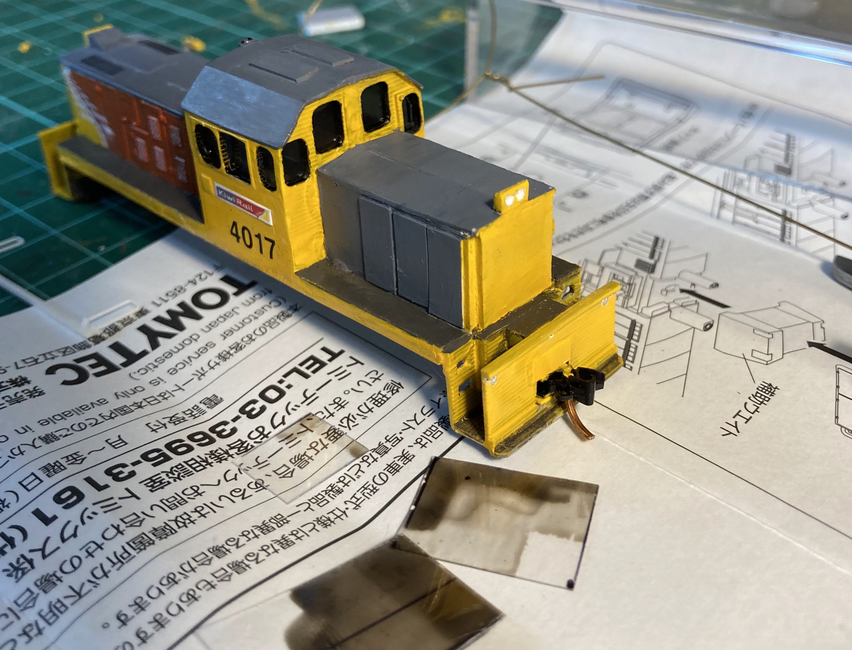
Glazing has been added inside the cab. I used some clear plastic painted with that semi-transparent Tamiya 'Smoke' on the 'inside' side of the glass. This was leftover from my 56 foot cars from a decade ago. I figure I still have enough to make another two or three or four cars so should do that (adds to project pile).

Leftover bits of glazing are on the paper under the loco. Those paper instructions were fished out of the rubbish bin in the hope of finding some clues as to how one might easily DCC the chassis. After a few minutes on google, it would seem most of the Tomix stuff isn't that easy to deal with, but I can see some possibilities.

Couplers had also been added, with a Microtrains at one end, and in what must be a rarity in custom made NZ120 and even in N scale locomotive builds these days - a Rapido at the other. This is so I can shunt (or at least 'tow around'), Peco wagons. The coupler is sprung and has that little tag under it so I suppose it could be used with some sort of mechanical automatic uncoupling mechanism operated from under the track, but that seems extremely unlikely to eventuate. I've never had much luck with Microtrains and magnets either, so shuffling wagons about with a little five finger shunting will be the the order of the day, if the DSJ sees much action at all! 

Dig that funky coupler:

The glazing looks better though. The DSG/DSJ have always had tinted windows, so my efforts here look decent from a distance. Cutting and sticking in pre-painted glazing is one of those jobs that looked like it would be quick and easy, yet it easily took an hour out of my limited mild-cursing budget. By the way, 'In the Loop' is back on Netflix.

You can still see through them but only just.


Thursday, May 30, 2024

DSJ Part 4. Decals.

DB returns after a few days of busyness:

A start was made with the decalling by using some spare old ALPS KiwiRail 'ferns' from my DX project of about a dozen years ago. Artistic license applies, as some KiwiRail DSJs have the fern this size, some have a smaller one placed high, and as the DSJ's paint design is asymmetrical, this also requires a 'reverse fern' on one end. 

I don't have a reverse fern, but on a visit to the local bike shop for the Tamiya paints recently, he had some Tamiya Decal Adhesive, so I bought that and used it to stick the 'top/printed side' down to the paint (glue side out) and this seems to have worked fine.

The KiwiRail logo patches were printed out in various random sizes on white glossy paper at The Warehouse. The large ones were a last minute addition... and even they are a bit small! When doing this, always make sure you (and they) are printing at 100% (no scaling). 

The glossy paper was a bit thick, but I managed to somehow 'thin it in half' with a sharp blade (top right logo above being split). These were attached with Selleys wood glue/PVA.


Numbers were from a MicroScale BNSF patching set, which were about the right size and a similar (but not quite right) font. Its really hard to install these so the numbers all line up. I scored C+ on one side and a D grade on the other.
 
All decals and logos have been covered with semi-gloss clear gently applied with a clean brush to protect them. The grey was repainted a slightly lighter colour in amongst this action after two hatches were added on the top of the cab. I'm not sure what these are for, as the DSGs don't seem to have them. Emergency escape hatches in case there is a need to ditch in water?
Plastruct blocks have been installed inside the tops of the hoods to fix the height of the model so that the headstocks clear the rails. The thing is sitting even higher than expected, so I might move the springs up on the bogies to fill the increased void.

A few dozen more tiny paint touch ups have also been done, and a start made on drilling some holes for handrails.

Saturday, May 25, 2024

DSJ Part 3 and a half. Coupler pondering.

DB Says:

Not much to report other than a few brief visits to the painting chair in recent days.

A structural challenge discovered a few days ago was that the coupler slot in this model is the perfect size for the underslung MicroTrains couplers that I have in the spare parts box, but it is at the wrong height, leaving the coupler face way too high. I have always used the 'MicroTrains standard height', because many of my wagons use their bogies as-is. Even the non-underslung versions won't work in this hole location.

Assuming fixing this was going to make a potentially fatal (to the model, hopefully not the modeller) mess, I pondered a few solutions before trying two tonight.

  1. Cut the coupler slot right down to the bottom (including taking out the shunter's step in the centre) by making two cuts with a Dremel disc. I worried this might crack the ends off or break something badly, plus it creates a dusty mess everywhere.
  2. Drill a bunch of small holes below the current opening with my Black and Decker drill and use a file or something to square up the enlarged hole. I did this, but didn't have to...
  3. ...because I used my tiny jeweller's saw to expand the whole thing downwards about 5mm in an approximately square shape. This was surprisingly easy, really quick, and not wildly messy in terms of dust.

A few pictures as the model stands.... Tamiya Panel Line Accent stuff was used on the end/top grilles at the motor end. There must be some variation in how this model is printed, as the top-port grill was well contained, but the Accent colour seeped out of the top-starboard one. Easily covered with some grey once it had set.

A triangular blob of yellow has been applied at this end, marking where a KiwiRail Fern will split the red and yellow. The DSJs seem to have their grey half at the short hood end, and the red on the motor end on both sides, with a 'reverse Fern' on this port side. 
The copper bogie 'springs' have been capped with a sliver of plastruct rod (about .020x.020 inches size). My big clunky fuel tanks have been removed from the shell. I'll cut them down and mount them on the chassis sides instead.
I've also painted the thick window edge cutouts black to make the cab wall thickness less obvious.
The white below on the end is a reflection! I have been contemplating another coat of the orange, as the grey Tamiya Surface Primer certainly takes some covering. I might try the white version once this grey can runs out.
As you might be able to see in this view, I finally had the yellow cab sides looking OK after four or five coats and touchups, yet the last thick coat obviously wasn't thoroughly dry underneath, and of course I stuck my mitts in it. Gordammit. 

Upcoming items on the agenda include finalising the chassis height inside the shell, adding couplers, and then finishing the shell off with handrails and decals.

Tuesday, May 21, 2024

DSJ Part 3. Paint.

A thin coat of Tamiya Surface Primer was sprayed onto the DSJ shell from the can (great stuff this) and left to set overnight.

The Tamiya acrylics don't really come in the right colours for us, but they are readily available throughout the country and pretty easy to work with.  So if you want more realistic colours, you have to mix paint shades. I've learnt from experience that doing this on a one-off/day to day basis is a mistake, as your next coat or touchup coat never matches your previous mix.

So I decided to make a whole tin of the right colours once and for all. I went out and bought a fresh (easily mixed, non gunky) X6 Orange, X7 red AND X8 Lemon Yellow.  After giving them a good shake, I tipped maybe 5% or so of the orange into the yellow to 'red' it up slightly (make it slightly less lemony), and did the same of red into the orange (to make the orange less yellowy). It doesn't take a lot to change the colour. I've put a dab on the lids below so you can see the before and after. Shake it all up well.

After two coats the result is seen below. One more coat is needed for the yellow. I'm not sure why I started painting the cab grey, a hangover from the fruit salad days I guess. You can see the DXC behind with its too-red shade on the long hood. I've cursed this since I did it.

I have almost 50 shades of grey, and randomly decided on XF91 for this. Lifecolour UA 722 (a sort of reddy, grungy grey was used on the walkways.

As always with the Tamiyas, a little paint retarder stops everything congealing too quickly and a little thinner may help too. Best to put a few thin coats on rather than one thick blobby one. Unless that is your intention of course, as was mine here on the side sills to fill any remaining gaps!

A few other things I need: Some half-decent brushes - a fiddly fine-pointed one for details, a big flat one for large surfaces like the roof and the sides (to avoid blobs and streaks), and usually one in between.

The magnifier is essential, and not only for those of us with eyes that don't work as well as they used to. Its amazing what a difference this makes to your painting (and modelling). Mine is from Lincraft and has LED lights in it (which I must find the adaptor for). I also have that black desk lamp. If you can't see what you are doing, modelling is really hard.

As my hands become wobblier (I shouldn't have had that second coffee today) I usually sit the model (or lean the hand holding it) on something (that raised clear box). The fewer moving parts to the puzzle the better when stabbing away with the brush. 

Sunday, May 19, 2024

DSJ part 2. Springs and things.

A few more hours were spent in the dungeon today. Panel details were added to the short hood sides. There should be three doors on one side and four on the other but I've ended up with three on each. They all had to be trimmed on top after installation because I seem incapable of making 90 degree cuts. 

The uneven sill undersides on the 3D print I should have dealt with using a big sanding block before cutting the shell to pieces. DSGs have smooth sides to these, but the DSJ has a channel section. I started making these by converting some 'I'-section plastruct into a 'C' shape by smoothing off one side, and was about to glue them in place but this would make the loco look too wide, so I've just glued a piece of plastruct along the wavy underside and have started filling the gaps (primarily under the cab) with that evil Squadron putty. This may take a few goes. 

I'll end up with a reasonably deep side sill, and you can see some pretty thick (.080x.080 inch) rod hidden underneath as well, because with the little bogies from the Japanese ND552 chassis, I need to fill the gap between rails and the shell with something or it will look like it is wearing short shorts with tiny shoes.

The real DSJ has the square indents on the cab for tablet exchangers, but in a different spot to the DSG. I foolishly filled in the DSG-located ones here. Silly, because I'm not going to be able to cut new ones in the right spot. I also started to remove the subtle strata on the cab roof with fine sandpaper.


The bogies obviously need to have coil springs added, but before this, the air tanks on the sides would need to be cut off. This daunting task was made easier when I began to make my first incision with a scalpel and found they just popped off (above). I'll add the tanks to the parts bin for some future project.

I've made coil springs from several things over the years. Little bolts with the heads cut off still look pretty decent on my FM van from the early 90s. I used little springs from couplers on the DI. This time I decided to wrap strands of copper from a wire offcut around a steel rod used to actuate points.
Mounted on some backing:
Not too terrible. They need a piece of plastruct rod on top (like the real DSJ/G bogies) to cap the springs, and it is hoped they will quietly fade into the underneath when some paint has been added. 
Oversized fuel tanks and undersize side ladders have been added, and everything is looking appropriately skewiff, even after the headstock was broken off and reglued in the hope of getting it a little more vertical. Some of this is due to wide angle phone lens distortion, but not all of it alas. There is also a little lever handbrake on the short hood corner below: 

It's almost due for a painting.