Monday, September 09, 2024

Turning CBs into coal wagons


DB says:

So excited was I at the rapid progress made in coaling up the CWs that a return visit was made to the dungeon to do the same with the CBs. 

All the CBs had thin card false floors fitted a dozen years or more ago, which were of various degrees of coal-tightness, but the gaps were easily plugged with dollops of PVA. One had been topped with an experimental application of builders expanding insulation foam, but that was a bit of a disaster as it takes some practice to tell how much - or more correctly, how little - needs to be added as it keeps growing for some time after you squirt it into place. This was largely cut away with minimal damage to the wagon.

Those cross braces between the hungry boards were an inspired decision many years ago, as they look pretty neat with coal across them.

While on a roll, I painted the CE, CW and CB Microtrains copper-coloured brakehoses, touched up any chips and scratches accumulated in the last decade, greyed up the CW bogies to match the other wagons, put an additional bit of panel wash weathering onto the CWs and considered a few other improvements. 

So that's 17 wagons for a decent coal train from 2005-2013, which covers the Tranz Rail blue through black, through Toll through KiwiRail period - dated from when the CWs got hungry boards until their demise. I think the red non-chuted DXs were probably gone off the coal trains by 2005 unless in use as an uphill leader through the tunnel as non chuted leaders on the eastbounds were still allowed then? A few more CEs and CBs instead of the CWs and the train would work up to the present time. 

Sunday, September 08, 2024

Turning CWs into coal wagons

 DB says:

Ah returning from the madness, I decide to give myself a day off. And as I haven't done any modeling for a while I decided to treat myself to a visit to the dungeon and tackle a quick and easy win if I could find one on the to-do pile.

Since I'd had some fun with CE coal hopper recently, I thought I might put some coal in my CWs, which are stil unfinished 15 years later...

Out they came. These are fairly light, but are weighted at the bottom, and as they are multi-piece castings, they have a nice smooth rectangular hole inside that would suit the false coal-floor which I'd never gotten around to doing..

A few strips of styrene were cut and contact glued inside.

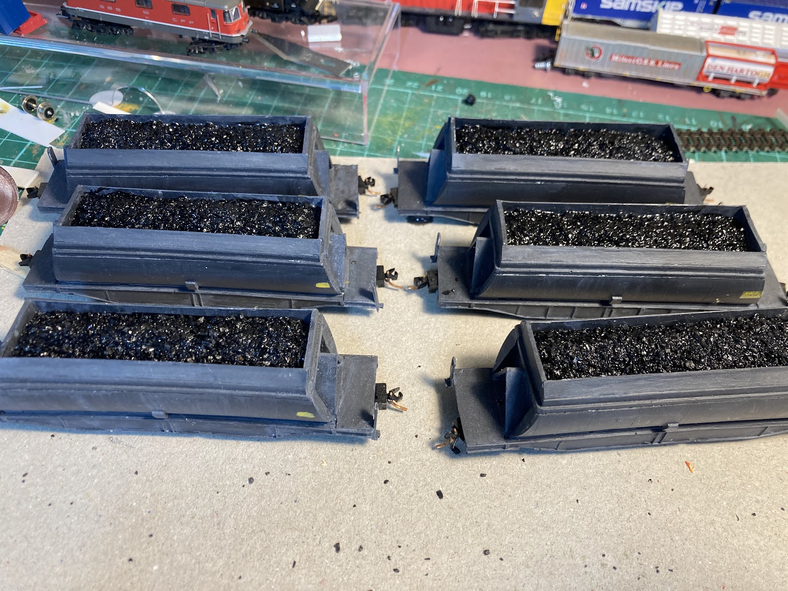
Then 6 false floors were cut to approx the right size and fettled as necessary. Only one of these wagons has any bowing in the sides which is pretty good after all this time. Coal was then sprinkled on and stuck in place (the same overchunky Peco stuff used in the CEs as I haven't gotten around to crushing any of it up into a finer grade). 


Not bad for an hour's work. One of these days they'll get some better numbers and their Microtrains orange brake hoses painted black. I think the bowed one is bottom-left in the pic above, but accentuated by the phone's wide angle lens.

By the way, I still have a bunch of spare CW parts (15 sides and 13 ends) that I'm unlikely to ever use, so if anyone wanted to donate a tenner for postage you could make up six or seven of these unfine wagons for yourself.

Wednesday, July 31, 2024

SI NZ120ers: Chch Train Show next year

 DB wonders out loud (and not having thought this through):

I can't be the only dude sitting at home with no layout but would love to run some trains... 

Are there many active (or potentially activate-able) NZ120 modellers in the South Island?

The reason for asking is that Christchurch has a pretty big train show each year, and unfortunately, as we don't have a Trackgang layout handy down here*, maybe we could make an NZ120 modular layout for me to run my big coal train on? 

Obviously its too late for 2024's show coming up in October, but if there was any interest, it's something we could target for next year.

This would give interested folks a year to knock a module together and scenic it, and in 8-9 months, if enough progress has been made, we could make a plan for how it could be physically set up, and then apply for a spot on the floor.

The October 2025 show gives some impetus to do that on a relatively grand scale, and a deadline to work towards to make it happen. 

My thoughts are a layout with modules based on the Fremo120 standards for new builds, although I see no reason why MMW modules and almost any other existing module couldn't be attached in some temporary but reliable fashion** to join in:  

  • DCC. Possibly with a straight DC operable branch hanging off Studholme if folks want to run DC trains) Or vice versa if DC participants outnumber DCC folks.
  • 1200mm track height from floor
  • Assuming there are not enough curves to make a traditional 'loop' roundy-round, we could have a long string of modules with a balloon loop at each end. I've started planning and procurement for one balloon end.
  • All NZR eras/periods/epochs, diesel/steam/electric and geographies would be welcome.
  • No TGV's please - slow to medium speed operation to... minimise derailments, respect other people's rolling stock and modules, and for a better look. 

During show hours, the layout is "for the punters not the operators" ...i.e. 

  • Layout is set up and tested before the doors open rather than spending the first two hours having the public watch you building things and trying to figure out how to get a train to run. 
  • During the open hours, there's always stuff going on, ideally a variety of different trains, train crossings, maybe the branchline is working or shunting, but there is always something running for the paying public to look at. 
  • Minimal fuddling around (i.e. if there is any shunting, it shouldn't tie up the mainline).
  • Using the most reliable stock (things that derail or don't run well get fixed, get cleaned or get relegated to the sidings)
  • We fix problems and derailments quickly and get things moving again.
  • It should be realistic, impressive, and show off NZ120's potential so more people join us for the next show. 
Then:
  • We can play with the derailing trains, complicated shunting with timetables and car cards after the punters have left. Or on the branchline if there is one and there are plenty of operators. But ideally over a few ciders after the doors close. 

So ... I have Studholme slowly under construction (3.6m) and have plans for two more modules to match it (one plain Canterbury Plains flatland, and a similar one with a low bridge which might be a curved module). So that could be 6m of modules to start with. Plus my balloon loop.

Ideally there would be another few "single track open mainline" modules. Maybe some have a culvert, or a road crossing, or a curve, or a bridge, or a tunnel or a cutting or an embankment. There might be a few 45 or 90 degree curve modules for variety (or if we end up growing too long for the space available). 

Perhaps someone might build two or three of these as a Module Set for scenic consistency. 

And the other balloon loop. 

If we had enough "open space mainline modules", perhaps someone might make another small passing loop station (Staircase, Seacliff, Tawhai, Kekerengu...). 

Sooooooo...... Is anybody out there interested in coming to Chch in 2025 to run some trains on a decent sized layout and have a few laughs?   And would you be interested in building a module or more?  


Friday, July 26, 2024

Only CE CEs are tasting like theees! - 4

DB weighs things up...

So the four CEs are looking pretty decent, but being 3d prints, they are featherweights that won't track well, especially when they are placed ahead of seven metal Trackgang CBs. 

I saved a few large chunks of lead rendered surplus from our roof, despite it being widely regarded as unhealthy (I'm not going to eat it). But, I don't know whether we cashed this in on a scrap metal drive or maybe its is hiding in a corner of a shed, but they haven't been seen for a while. 

Anyhoo, the CEs are made with a nice slot underneath them that might take something straight and weighty. This slot is obviously really low, and a low centre of gravity usually helps things run nicely. 

So I bowled on up to one of our local engineering shops and wondered if they had any small steel square rod for sale, fully expecting them to say "no, you idiot, of course not". As is almost always the case when I ask such a stupid question, the answer is usually some form of "well, you could perhaps use ..."

And so they have something called machine key steel, available in various sizes. When I had this genius idea, I had failed to actually measure the CE's slot beforehand, so was left scrambling. I bought a 3mm and a 5mm square piece. The 5mm was accidentally perfect. 6mm would fit, but this would obviously hang 1mm lower, so I'm glad I ended up with the 5.


It's pretty tough stuff, and my hacksaw seemed to be fighting a losing battle, so I bought out the spinning wheel of death with one of those really skinny cutting wheels about 2cm across. Cuts were slowly eroded into the steel on all four surfaces until I could snap off each section. I aimed for four 52mm lengths.

Installing:

And as you can see, you can barely see the steel from normal viewing angles. I'll paint it black once the glue dries. Overall these are still a little lighter than a CB, but should be heavy enough for the job. Must weather the bogies too.

Sunday, July 21, 2024

Studholme 8 - All together now...

 DB continues:

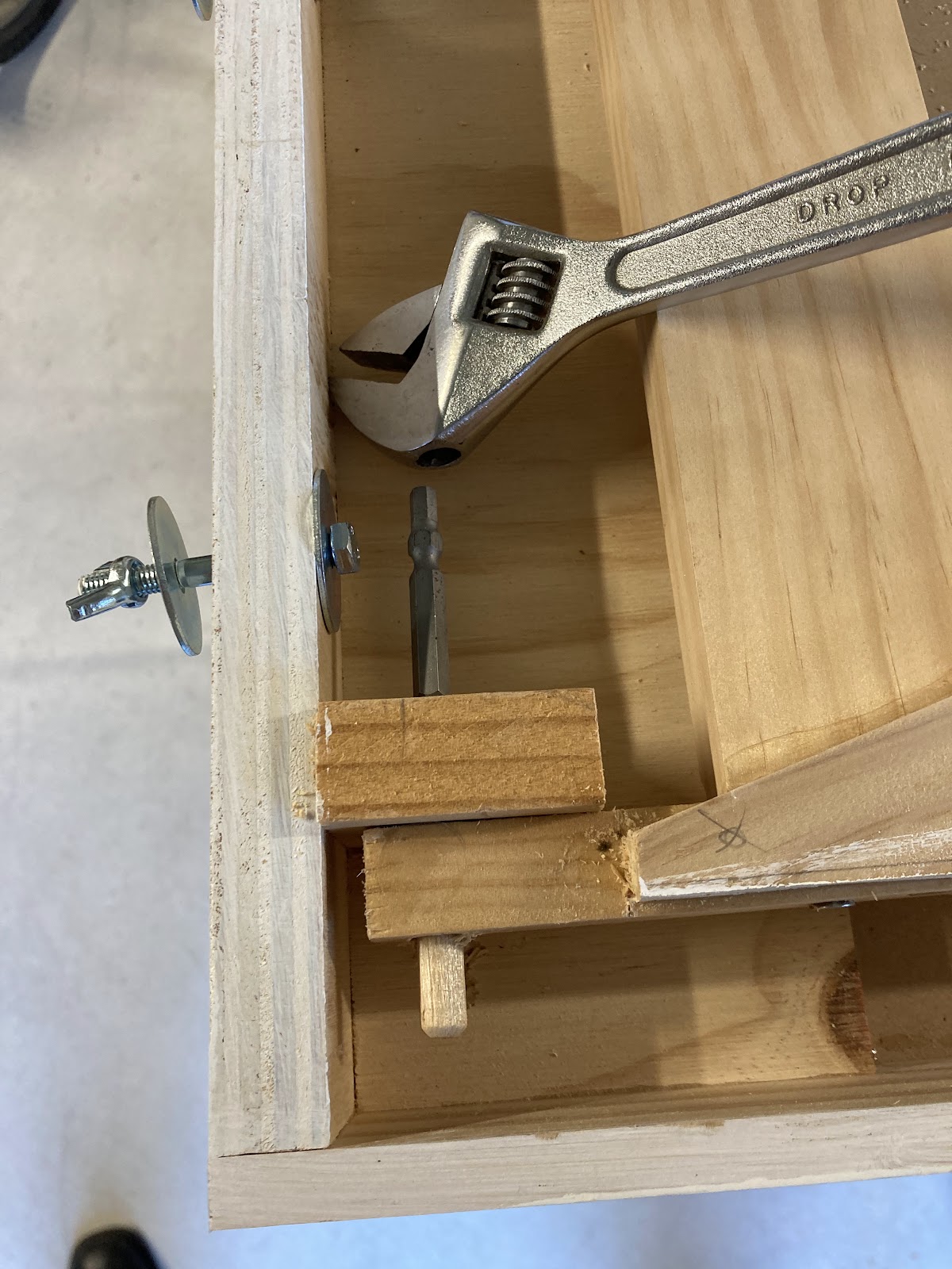
Buoyed by the success of last night's bracing post, I went down to Mitre 10 and bought some 50mm M6 bolts and wing nuts and an assortment of washers, which let me complete the module's two legs with their fold-in braces. These braces are screwed to the legs at one end (with a bigger hole in one of the two bits of wood for some swivel) and M6-bolted to a little tab on the module at the other end. The braces are all made from the same 18mm square 1.2m long sticks that were procured from Bunnings for legs and braces when this all started.

This enabled me to sit the Centre module on its legs for the first time, with feelings of joy and a sense of pride that I expect a father feels when their first child takes its first steps. 

Like that child, the module was a little wobbly. Perhaps a little too wobbly for my liking, but at least it didn't fall on its face, throw up or poop itself. 

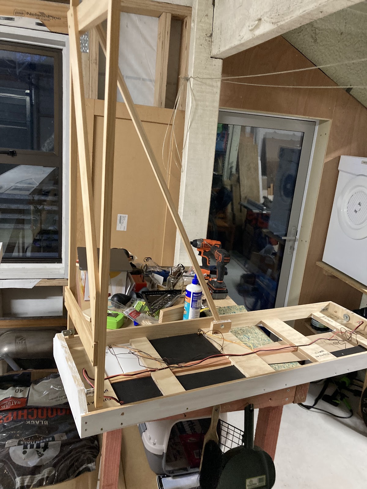
This wobbliness likely stems from the braces being relatively short. So a new plan was hatched: detachable longer leg brace sticks that can be stored within the module. So I decided to add the longest brace that would fit (diagonally) under the module 'lid' of the South module, with the module legs folding up to keep the brace in place during transit. This brace would be bolted with M6s and wingnuts at both ends.

This was proceeding to plan rather swimmingly, all too good to be true when it dawned on me that (six months ago) I'd put this South module's leg at the inboard end of the module, where it would mate up with the centre one with its two leg sets and leaving none at the outer end where support was needed!! D'oh! And I'd made a really nice job of this one too - better than the funky North module leg. Maybe this was supposed to be the module with two leg sets and not the Center one.....


So the wooden dowel pivots were knocked out - always use the correct tool (as above, "dear, where's the hammer?"), the leg was repositioned to the correct 'outer' end, and the brace added. 
This single brace felt a lot stiffer than the twin wee braces on the middle section. So now for the acid test... the South module was plugged into the Centre module. 

More pride and joy! So much so that I decided to reattach the legs of the North module (which I'd never been that happy with, but hey, they work) and put a similar long detachable brace on it, wingnutted at both ends. 


Ooooo. Finally, Studholme is back together again, and with those two long braces on the ends, it's actually pretty solid. The two end modules with their single leg sets are nice and light too. It all looks a little skewiff in the picture above, but the adjustable feet at the ends of the legs have since been wound in and out to level things up.

As an aside, I remeasured the length of the three passing loops - they should be able to hold a 2.1m train each. That sounds like a lot until I went inside to measure a pair of DXs and some bogie coal wagons. That is a 15 wagon train plus two locos. Maybe 16. 

Which again, sounds fine, but I already have a few more bogie coal wagons than that, with bits for another six. C'est la vie, whatever that means. If this ever sees any action at a show, and if it turns out to be a little short for the trains that want to be run, a medium length four track section could be added later on between the Centre and North modules.

Saturday, July 20, 2024

Studholme 7 - The quadpod

DB Says:

This blog post was started six months ago, but a other projects and a mental block have kept me from making much progress on the modules.

The first module that I started had some primer belatedly applied onto the bits that aren't tracks, and the single track arriving in from the north was cut square(ish) with the faceplate using an unruly dremel by your half-blind correspondent in the dark.

Results: Not completely terrible, but also, not as perfect as had been expected. Might need an expansion gap added yet on one side and its rail pushed closer to the edge. Having said that its probably fine as long as the adjoining module isn't similarly afflicted. I suppose cutting it a bit long and filing/grinding it back would have been more sensible.


The other tracks remain extended beyond the layout edge so they can be glued down to the neighbouring module in due course and then cut.


Another disturbing development at the north module set end was disclosed by the arrival of a passing set square: 


I think this is because the track isn't perfectly in the centre of the module at the very end. It might need to be swerved out to the right at the bottom of the picture. Fortunately it's only lightly tacked down.

Also fortunately, I haven't drilled the holes at the outer ends of the module set yet. Measure 8 times, cut once I think the old saying goes. 

....Then things stalled for six months with the mental block.

This is because at least one of the three modules needs to have two sets of legs, ideally the middle one, which would give me a setup like this:

But fitting two sets of legs, folded/stacked on top of each other into a thin module was going to be tough to fit, and Then Mr Pythagoras gets in the way when it comes to the angled braces, which I wanted to have attached and foldable for transit, but they should ideally be as long as possible.

So after putting off this task for months, tonight I went down to the garage and hammered out a thinner set of legs that fold up OK.  I even have a 'rest' for the lower legs to sit on (so they won't crush the upper ones) and will add a little twisty-movable 'key thingy' into it so everything stays locked in place during transport. As these three modules are intended to be stacked, I don't want the legs crashing down onto the buildings and scenery of the module below it.


It works! (not enough hands to take a picture and hold the legs at 90 degrees).

I then mounted my first angle brace (below). Just need a thin bolt with a wingnut to complete that, and then I'll build more using this idea for the other three leg sets.
A few thoughts on my spindly legs. They seem solid enough, but the proof will be when this is set up and used. Too much pressure on the wrong place could be a problem, with the holes drilled for the hinge pegs obviously the weak spots. We shall see. The thin legs have kept the modules fairly light, although this centre one with two sets of legs is getting heftier than expected. Still, it's completely self contained (carrying legs, braces and all).

Thursday, July 11, 2024

A little off the sides

In my last post I showed a picture of where I was up to with my EE set. Having a look at the painting on the headlight end I noticed one night last week., I noticed that if the silver line I had painted level with where the side met the roof, the paint line came down only about 2/3rds of the way down the light cowls. 


This didn't quite ring true in my memory and so I went back to photos of the real thing to check.


 Ok, so a quick look shows that the roof should be painted down to level with the top of the doors.

Easy enough fix.


 However it still didn't quite feel right and perusing my collection of pictures from trawling the web I discovered the truth...


The roof is actually curved right down to the top of the doors. The shiny strip above the doors appears to be a trick of the light or the cleaning machines they use very sporadically.

Out with the file and fortunately there is enough fat in the print to round things down  to where they should be.


This is my test shell and its proved to be a bit harder to fix my 3 other tops with their new ventilators in place, and I'm also wondering about the toxicity of the resin dust.