Thursday, December 28, 2023

A 3 Foot 6 Interlude - 3d Printed bits

DB ponders and then stirs...

Two things NZ120 needed twenty years ago, were a simple module standard (done!) and some quick, cheap, quality wagon tops. Maybe nothing too fancy, but something to give those less comfortable with scratchbuilding the ability to easily make a train that looked 'right and proper'. At the time I wondered if this might have to be a run of injection molded LC tops, but time has moved on, so technology and the efforts of a few CAD designers has solved the problem.

While we made some initial forays into CAD and 3d printing/laser cutting 10-15 years ago, it was Peter Bryant and his KiwiTrains blog who really got the ball rolling big time. Designing a wide range of models quickly for NZ120 and other scales, he made them available on Shapeways. Soon other designers joined in, and I bought a few Shapeways prints more than ten years ago. 

Shapeways items always had challenges - expensive, variable quality of finishes, plenty of print strata, and of course they had to be mailed from abroad, so they were not the solution for the impatient or thrifty. 

In the intervening years, initially expensive DIY home filament printers that spat out plastic spaghetti have given way to higher quality 4k and better resin printers.

Lewis Holden decided to bypass the Shapeways issues by licensing the designs that have already been drawn, adding a few of his own, and printing them domestically as 3 Foot 6 Models.  So you can now get good quality 3D printed NZR models in NZ120 (and other scales) with a much faster turnaround time and low cost shipping.

Sunday, December 24, 2023

Studholme 5 - Finishing off topping it off.

DB finally finishes off the top. 

Having had a broken and oddly shaped leftover piece of dark coloured hardboard(?) lying around, which happened to be the same depth as the 3mm MDF, and was 1200 long, I decided to use that to deck the centre module. Yes, that stuff is even worse than MDF and will be impossible to staple into, and almost impossible to bang things into, but it will do. And I had it already. So I cut a side straight and used the table saw to make a 400mm-wide piece.

The areas at one end that will be fields then had to be cut away, to leave a raised trackbed (to match the North module), so this was measured up and the tracks were laid out to see what needed to be removed. The southern end of this is a full width yard, to match the South module, so nothing had to be cut there.


And a final test to check things line up along all three modules: 

Now that the glued-and-screwed top deck has dried, I can work on mating the module set together. There have also been ongoing experiments with legs, points and other details, and these will be reported on in the upcoming week or so. 

The next modules after this will be constructed in a more logical build order: frame, decking, undercoating, mating, legs, track, electrics!

p.s. Merry Christmas!

Thursday, December 21, 2023

Studholme 4 - Live Wires Below

In which DB still can't weld wires to save himself.

While you were sleeping, I have been undertaking a few other experiments, but they can wait for another episode. Some tracks were stuck down with contact glue and the odd staple, and the next step was to attach some wires to the tracks and see if the thing works. 

I like to generally use red and black wires for my 'bus' wires under the layout ("blacken and read out" is how I remember the colour for inside and outside rails). But prefer brown (it's a shade of red!) and black for the droppers attached to the tracks. This is because in the past, red wires have show up like dogs proverbials above the tracks. Yes you can paint them later, but this is my shortcut. 

To further make things easier underneath, all the inner rail brown droppers were placed about 5cm from all the outer rail black ones. This makes it easy to link them up to bus wires and also eliminates any risks of shorts since I was too lazy to use that shrink insulation. I stapled the bus pair in the correct orientation, and once confident with the operation of the whole schemozzle, I will put some dollops of hot glue to fasten them to the boards.

When soldering, as you can see, I come from the "the more the merrier" school of solder dolloping.


That didn't take as long as I feared. The switches on the bottom edge are for powering the Peco electrofrogs, which I'll save for another episode. I have also decided to isolate the 'island platform loop and branch, and will have a DPDT switch so this set of tracks can be powered by the main power bus, or by a separate controller (which could be another DCC booster or straight DC).

OMG!! It works. And even before a dusting with the Peco track rubber, the DF ran incredibly smoothly at super slow speeds over all the points. By the way, all this track has been recycled from previous layouts, so all is likely between 15 and 25 years old, that monty-sized bus wire was underneath Tehachapi until about 2008, and of course that Digitrax dates from about 1996.

A little shunting was even possible, very little, given the very limited backshunt available!

I followed Darryl P's advice and put a coat of primer on the south end yesterday!

Wednesday, December 13, 2023

Studholme 3 - Topping it Off

 In which DB attempts to catch up with himself:

So with the three Studholme Junction module frames completed in exquisitely-cut plywood, the next step was to put a top on them. 

While I'm not wedded to the idea, the Fremo120 standard suggests a 3mm thin layer of wood be placed between the track and the 'base' as a solid subroadbed to provide at least a minimalist amount of scenery relief even if nothing else was attempted, such as is likely here on the vast flat plains of Studholmeland. No yawning gulches or tunnelled mountains here.

I still have bad memories from decades ago of MDF and chipboard turning into spongecake when water is applied, so I might not be able to face gluing the ballast down... But be that as it may, I headed down to the local Mitre 10. Only to find they don't carry 3mm MDF. 

However there was a 1200x600 sheet of 3mm MDF next to some thicker MDFs. "How much is this 3mm sheet, its just what I need for my model railway and, there doesn't seem to be a SKU or barcode nearby?"  The reply was "No, we don't stock 3mm, that's a bit of packer to protect the sizes we do stock during shipping. You can have that."

So, problem solved, and economically at that. Especially as this was listed at 1200mm long and my modules are ostensibly 1200mm long, and this might be wide enough to deck the 'north' and 'south' modules. This is because while the south module's track with the Foley's road crossing needs a bit 400mm wide, the the north module is just a few tracks wide. 

I laid the tracks out for the south module on the MDF sheet and pencilled around things ...

...then got to work with a skillsaw and jigsaw, and was pleasantly surprised at how tidy it came out. 

I used a mouse sander to bevel the top corners of the cuts to give some shape for the ballast/mini embankment profile (otherwise I would have a sharp edge to these raised pieces that might more obviously show through the ballast... plus it gave me a chance to straighten out any imperfections). I did the same thing with more gusto to provide a little camber on the top of Foley's Road.

The MDF was then glued in place on the frame and weighted down. This is the 'south' module again in the pic below, the single track from the south coming in from the right, crossing Foley's Road (the 'T' running from side to side) and then expanding into loops either side of the mainline etc etc. Under the bright purple bottle centre-bottom you can see the trackbed for the Waimate Branch curving away from the island platform:


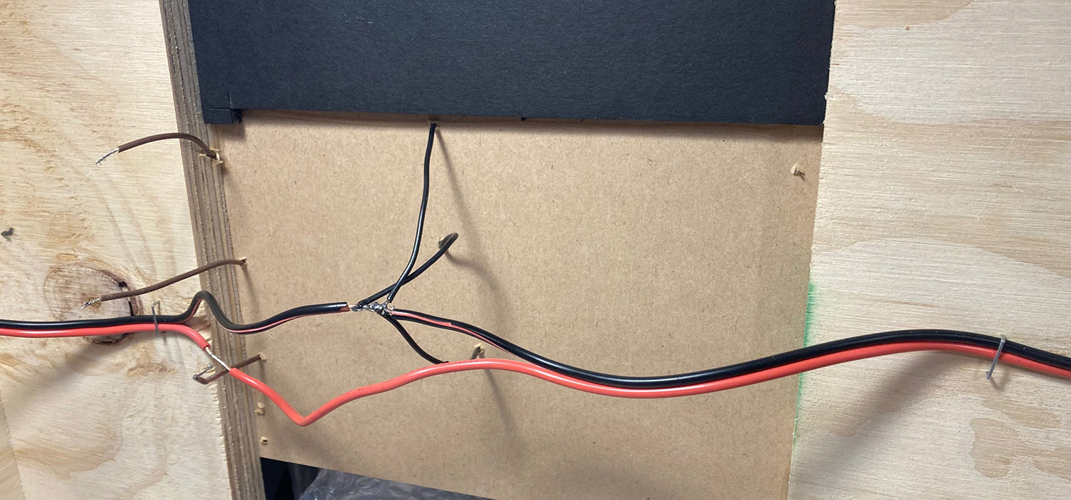
With two cross pieces of ply in the frame underneath, I thought the MDF would be strong enough on its lonesome. It is on the wide (more fully decked) areas, but under that single thin bit of mainline (and any other bits that seemed to move under an applied finger) I glued a stiffening piece of scrap thin wood underneath (I know N scale mechs don't weigh anything near the weight of a finger with me leaning on it, but better safe than sorry):


I filled the holes with spare foamboard. These sit at the height of the frame, 3mm below the trackbed, and this will all be painted and covered in scenery representing farm fields later. Second awesome purchase this month was a builder's 90 degree square thingy. What a great device for all sorts of things (including as a straight edge to cut foamboard rectangles. 

The centre 'station' module, with the station, goods shed and several sidings out both sides, will be almost fully decked, so I will have to go see if I can locate another packing piece in another Mitre 10 wood bin and then go and find that helpful staff member again with my lost and bewildered face on...  

Apparently the two 1200mm's referred to earlier on the 'south' end module were not quite the same length, so I will need a thin strip of MDF (or more likely stripwood) as a filler at the inboard end. I don't think this will be a problem at all.  For the 'north' end module, I learned my lesson and buzzed the MDF in half at an unimportant place (not under any points or rail joints but on top of a piece of ply), so I could push the MDF right out to the endplate edges of the module. In the pic below, the end closest is being glued, and the bit at the top is just sitting randomly, awaiting its turn to be moved in and glued down. This is where the mainline from the north splits into the loop, and then two points spawn the island platform loop and the goods shed/loading bank loop, with those four tracks running towards centre 'station' module.  The small gap between these two halves of MDF will be filled with a bit of balsa or even ballast later.

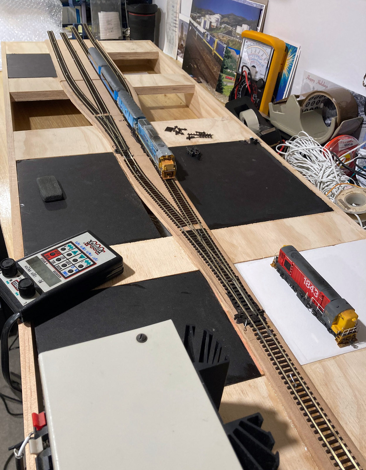
In the pic below, the three Studholme modules meet for the first time. Why hello there. The centre station module still yet to be decked, several weeks after these pics were taken!