Well, its that time of the year again when I get to sit down and see where the last 12 months has got me.
12 months ago everything was going into boxes in preparation for the great move north. This has worked out very well for us personally and for me professionally. Its nice to work somewhere where one is appreciated and the atmosphere is rather more fun. The lady of the house has also completed her degree this year (only 20 years in the making) and is on to further study next year. So baring family fires and some health issues its been a good year all round her at Schloss Dandruff
Layout wise tracks were still getting made. I could run a loco a whole 7'.
Moving on 12 months later and short of the turntable and the main join between the 2 northern boards its pretty much done. The major other parts to do are checking the track is all in gauge etc and installing the booster for the DCC set up.
In the loco and rolling stock department, there have been a couple of oddities in the Price Cb and rail truck that saw the light of day. On the real rolling stock front there was pretty much zip. The is no Ew to grace the rails, and the large steam locos remain firmly on the drawing board. With the wagons the main problem I face is decent wheels to an NMRA standard on a short axle. I can't get hold of any of the newer Dapol or Farish stuff (and believe me, I've tried) which have the right wheel size. Any US stuff is just too small (5.5-5.7mm vs 6.2mm and to me yes it does make a difference). The 2mm stuff is very pretty, but my track making skills are not quite up to it. However I'm looking forward to the etched underframes from MMW so that may spur me on in the new year.
So what will the new year bring? I'm hoping for some more etching being done, and possibly even a couple of kits or something. Certainly completion of some of my loco desires for Paekakariki. I'd like to think that by this time next year the layout has moved on a bit more
You'll have to excuse me now. Its raining and I'm off out to the Man-sion....
UPDATE; As an aside, does anyone have any suggestions for a cheapish USB web cam? I'm just experimenting out in the shed and the one I own is complete crap.
Saturday, December 31, 2011
Friday, December 30, 2011
Upstairs and downstairs - DG2376
DB says:
I added a roof to the DG today [which is probably a week ago as you read this as I did all this DG stuff over the Christmas weekend] using some 1 inch dia plastic irrigation pipe leftover from the AO cars.
After a lot of dremeling and sanding it's almost done. The real thing has an unusual cross section (curved on top but with steeper sections at the edges, but this will do. Its probably a smidge tall, but so is my other DG. Not shown in the mockup pic below was the removal of a section at the very back of the roof on the port side (avast!) for the dynamic brake roof shutters. I'm sure that will be visible in a later picture.
With that almost sorted it was time to go 'down there' into the netherworld of chassis surgery. The 'new' Kato Pa-1 chassis is DCC friendly, but longer than the old Kato/con-cor ones, so needs a few minor alterations. Luckily, it comes apart very easily:
A little nipping and tucking later and I have reduced the overall length by shaving the ends and removed some of the PA-1 fuel tank as the DGs had tiny tanks:
I then used a marker pen to blacken the lower surfaces of the metal casting that might show under the NZ120 body.
Luckily, the PA-1 bogies are almost perfect for a DG. They are a tiny bit short in bogie wheelbase as almost all N scale mechs are for us (they should stretch further inboard towards the fuel tank), but the details are almost perfect. Technically the PA-1 has a pair of tiny coil springs on the outer of the equalizing beams where we had 1 coil spring, and the top of their bogie main casting has a tiny curve on top of it above the centre wheel, and our brake cylinders are more complex, but none of that bothers me enough to make any changes to the Kato items supplied.
p.s. Except for the bogie mounted sandboxes that one batch of the DGs had (the others had sandboxes hidden behind the headstocks)... I think perhaps all of the late-surviving locos had bogie sandboxes, but just at the '4 corners' of the loco, not one at each corner of each bogie.
Thursday, December 29, 2011
Summer
While kiwibonds freezes in a North American winter and has modeling time, here in the south pacific its much harder to justify heading out to the shed for a few hours given its been blue dome weather for the last week or so. Yesterday was gardening and fishing after getting new tires for the car. Hence we get staggered posting about how to build a Dg which I think is now finished, but still has a week to run cos I'm lazy, and if we posted it all in one go then I would have to come up with something else. I have also been rebuilding an old laptop (an Eee 701) adding a new operating system and more memory so that I can use it when away from home.
Fortunately the weather appears to be packing in (slowly. its suppose to be raining now, but like everything else its on a go slow as well), so I'll be able to run away out the back for a while, where many jobs await.
There has also been some discussion in the peanut gallery about entries for convention competitions. Given that its only 3 months away (REALLY) you should all be planning your entries now. I'll do a separate post on reading the rules and whats involved in doing as well as you can.
Wednesday, December 28, 2011
Gweilo - DG 2376
DB says:
The slang term for a westerner in China is gweilo (bignose). Of course you would never call my nose big if you had met an English Electric DG loco. Aiiiyaaa!
I began by making the front face, which on a DG slopes back a little from the vertical and is graciously curved across the front and suddenly more sharply at the corners. A few plastic corner posts and a .5mm sheet rendered a fair representation of this once sanded down and stuck together.
After letting that set for a while I started on the top section. This is surprisingly tall on the prototype - the top of it comes up to the height of the top edge of the cab side windows. To make this I stuck two pieces of 2mm sheet together and began filing. As with the front face, there is a nice curve all over the top with a tighter radius curve at the corners. To make things even more difficult, the top slopes down slightly toward the front. Again, I think the Trackside kit seems to do a good job of capturing this from the pics I've seen (and again, I should have bought a Trackside nose rather than making my own, but that's stupidity for you).
After a considerable period of dremeling and sanding I attached the nose-top to the body only to find it was too tall. The sanding crew were roused from their slumbers and eventually I was happy enough with the general shape. A little modelling putty was applied in the seams and hopefully some paint, hatches, doors, headlights and handrails will complete the illusion of fidelity.
I highly recommend the April 2002 NZ Model Railway Journal's article on DG locos, which has an excellent range of reference pictures and plans.
Monday, December 26, 2011
Rumble in the Jungle - DG 2376
DB says:
Well I finally made it to my nice clean freshly carpeted train room last weekend, but struggled to find my knife. As such, my NZ120 pilot light was unable to re-ignite any of the half finished efforts that I did find. Somehow I got fired up enough to make some serious progress on a long running Z scale project and kitbash this N scale freak:
No, it's not exactly NZ prototype, but you might be interested to hear that I bought an N scale Kato C30-7 a few months back as I've always wanted one of these UP C36-7s with their lumpy Dash-8 style dynamic brake box. Its not a perfect model, but it will do me. And most importantly, today, when I did find my modeling knife, my modeling juices were already flowing.
Another thing I stumbled on last week was a bunch of DCC friendly PA-1 chassis hiding in my drawers (my desk drawers you understand) and this feeble piece of origami:
Which you may remember from a long-ago post on the use of modern technology in NZ120 modeling
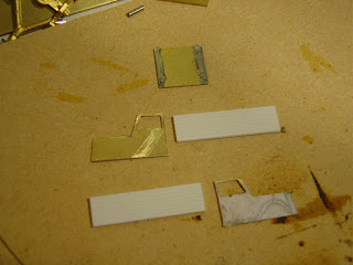
I made this home-made brass etch by starting with a plan in 'negative form' (i.e. black everywhere except where the etch lines should go) printed onto cheap photo paper (because it is coated paper) in a [Dr Evil voice] laser [end Dr Evil voice] printer. Then I turned the printed paper upside down and carefully ironed the DG plan onto some .5mm thick brass strip using an iron (strangely enough).
Aaaaaaanyway, I thought I might see if I could put some lipstick on this pig as I really should have a model of DG2376; especially now that as I type this blog post, the orientation of the real one is in doubt thanks to the Dec 23 Chch earthquake blitz. I feel for you, Christchurchians...
Since the 'rear end' as I etched and folded it was a bit wide, I cut it out to give me two sides and then made up a plastic replacement back to match my recabbed NZ120 DG 2330. I then managed to glue all of this plus a front headstock together in a geometry that isn't too far off flat and square.
Then it was time to start the nose. Having studied DG noses inside and out for many years I can tell you they are difficult to understand in your head, let alone model, and the published plans can be misleading. The Trackside NZ120 DG seems to have one of the best nose shapes out there from th epics I have seen - the face seems to have the right angles and curvature although the front windscreen face should be sloped more and moved rearward maybe a mm or two which would make the the whole snout look the right length.
Well I'm about to dive in and attempt this with layered-on chunks of plasticard... It might have been smarter to buy a Trackside nose :)
Well I finally made it to my nice clean freshly carpeted train room last weekend, but struggled to find my knife. As such, my NZ120 pilot light was unable to re-ignite any of the half finished efforts that I did find. Somehow I got fired up enough to make some serious progress on a long running Z scale project and kitbash this N scale freak:
No, it's not exactly NZ prototype, but you might be interested to hear that I bought an N scale Kato C30-7 a few months back as I've always wanted one of these UP C36-7s with their lumpy Dash-8 style dynamic brake box. Its not a perfect model, but it will do me. And most importantly, today, when I did find my modeling knife, my modeling juices were already flowing.
Another thing I stumbled on last week was a bunch of DCC friendly PA-1 chassis hiding in my drawers (my desk drawers you understand) and this feeble piece of origami:
Which you may remember from a long-ago post on the use of modern technology in NZ120 modeling
I made this home-made brass etch by starting with a plan in 'negative form' (i.e. black everywhere except where the etch lines should go) printed onto cheap photo paper (because it is coated paper) in a [Dr Evil voice] laser [end Dr Evil voice] printer. Then I turned the printed paper upside down and carefully ironed the DG plan onto some .5mm thick brass strip using an iron (strangely enough).
This process melts the plastic laser toner onto the brass, and annoyingly, while its at it, also has the effect of sticking the paper sheet to the brass. But never fear for once its all cooled down, you can put the whole mess in water and soak off the paper thanks to the photo coatings, leaving the brass nicely coated with black plastic toner except for the grills and windows which will be etched out. This you do in a little tray with some acetone and acid and a turkey baster. Of course I'm not cleverly making this up - you can Google "toner transfer brass etching" if you really want to see how this is done in more detail. It works.
This was a reject sample - note no toner on the top edge of the piece due to poor ironing skills! This could be saved by using a permanent marker to draw over the bits you don't want etched.
Aaaaaaanyway, I thought I might see if I could put some lipstick on this pig as I really should have a model of DG2376; especially now that as I type this blog post, the orientation of the real one is in doubt thanks to the Dec 23 Chch earthquake blitz. I feel for you, Christchurchians...
Since the 'rear end' as I etched and folded it was a bit wide, I cut it out to give me two sides and then made up a plastic replacement back to match my recabbed NZ120 DG 2330. I then managed to glue all of this plus a front headstock together in a geometry that isn't too far off flat and square.
Then it was time to start the nose. Having studied DG noses inside and out for many years I can tell you they are difficult to understand in your head, let alone model, and the published plans can be misleading. The Trackside NZ120 DG seems to have one of the best nose shapes out there from th epics I have seen - the face seems to have the right angles and curvature although the front windscreen face should be sloped more and moved rearward maybe a mm or two which would make the the whole snout look the right length.
Well I'm about to dive in and attempt this with layered-on chunks of plasticard... It might have been smarter to buy a Trackside nose :)
Saturday, December 24, 2011
Saturday morning
Well, with the festive season upon us, I have not had much of a chance to do any modeling this week. I've also been expending some energy in getting an old net book up and running. it works, but I'm having problems uploading a new operating system onto it. I'm sure I can sort it out, but its just taking time.
I guess its also the time for an end of year wrap up, so lets get some discussion going. What are your high points and low points (in modeling only please.). Bouquets and brickbats could get a bit too personal.
For me the high point(s) were.
-Getting my track making skills to a point where I can now make good looking track that seems to work well. Being able to demonstrate at shows that its not actually that hard to do.
-Getting back into the show scene, and catching up with friends old and new.
-Making some of the smallest NZ120 locos with some more in the planning stages.
low points were a bit harder and basically boil down to not progressing some projects along as well as I would have liked. Things that spring to mind are the Ew and Ka (both with none). I think this is down to the location of the Man-sion. At Chateau dandruff in Nelson 'Der room' was inside the house, and I could hold conversations with the lady of the house. Now I'm off out in the back blocks and its a bit harder to spend lots of time.
So, we throw the comments section open to the cheap seats. I'll even invite modelers from other scales to post (isn't that generous of me). Just keep it (reasonably) civil.
Friday, December 23, 2011
History is alive and well....
Armless_Fet writes:
I was wandering aimlessly into work the other morning and saw the interior design team were in with all their tools in the lobby by the lifts. Sitting on some trestles was a long plank of varnished wood. Didint really think much more of it, until I left for lunch and was greeted by this:
Gobsmacked I was! As a student of fine locomotive design, I knew that is from Sir Nigel Gresleys A4 locomotive built in the 1930's.
I've always had a soft spot for the A4's....they looked much nicer than the LMS "Coronation" streamliners, and Sir Nigel's influence lasted even after his death....apart from Thompson ballsing about, the Peppercorn A1's are still the best looking 4-6-2 locomotives to come out of the British Isles.
And for those who love all things steam, that sounds like an open invitation for an argument....Begin!
Tuesday, December 20, 2011
Short update
Just a quick note on where things are up to.
I've added the canvas cover to the rear deck, and added the pickup wires back into the guide holes. After cleaning out the inside of the syringe tube with a piece of broken fret saw blade it has taken it's first stuttering steps last night, which bodes well for the rest of the build once I get the pickup on the rear axles fixed and some more mass into it.
Monday, December 19, 2011
When the hell did THAT happen?
(In which our hero discovers that he has actually become surprisingly competent at some things without noticing).
When we left our last episode the mech was whirring away happily without getting far, and the cab sides were cut out. Another session at the workbench and things moved well along, without many burnt fingers. I should have taken pictures along the way, but as you are all well aware I just don't roll that way. Suficit to say there was some cutting andsoldering and filing interspersed by the sad little plink of yet another fret saw blade giving up the fight.
The cab actually came together surprisingy easily considering its a collection of odd shapes of metal. The plastic deck at the rear was somewhat simpler to do. Personally I was astounded as it is the first time I've tried to do anything like this in brass, and it all came together well without unsoldering itself once (though it did get quite hot at times). As for the atuall prototype, well its a truck of some sort....
I have removed the pickups for the time being as I have to work out where they will go with the lid on.
Next up the obligatory photo with the Cb for scale. I had thought the cab was going to sit too high to clear the front bogie, but it looks OK. The front bogie has now acquired some bush workshop 'wood' frames to cover up the rest of the bogie bits. There are also the beginnings of some weight in the back. There is plenty of space for more weight in the cab (OK, plenty is a relative term) and also under the canvas top. I must go and find out if you are still allowed to buy lead in this country, of if its been banned by the environmentalists.
Final shot today shows the addition of a dumb buffer (on the off chance that it might have enough grunt to actually move something else under its own power).
Not bad for 5 hours of work over 2 days. Not so good for anything important getting done on the layout....
UPDATE; in response to a question, here is a general idea of how I did it. Basically it was sheer dumb luck.
looking from underneath. The top of the hood is shim brass sheet that is curved over and soldered on each side. I've then put a dashboard piece in that provides the bottom of the windscreen.
The top side. Here's where I got lucky, as I just soldered the brass dashboard in and the solder flowed into the right shape. I think its something to do with the silver content. I'd give you a scientific discussion of this but I'm worried about people falling asleep at keyboards, and waking up with a key imprint on your forehead. It does work though, and I just had to do some cleanup on the ends with a file.
Sunday, December 18, 2011
Distracted
Well, with all the best intentions I ventured out to the man-sion yesterday afternoon to work on Paekakariki (which has now acquired italics to show its importance). Unfortunately I was distracted.....
I have made a few alterations from previous pictures. The rear underframe has been built up from a couple of bits of 0.4mm PCB. The spoked wheel has been replaced by a plain 7mm one though I might replace it with a smaller 6mm one as it doesn't quite look right at the moment. I was pondering how to arrange the power pickup from the front bogie. There is quite a bit of swivel required for the tight curves and I was not happy with soldering a wire onto the pickup as I had done with the Cb. A moment of clarity gave the solution. I have some bits and pieces of syringe needle as it is a good source of small tube. A short piece of this was soldered to the pickup stub, and then a piece of phosphor bronze wire was slipped into the hole (a loose fit) and the other end soldered to the frame. This set up actually works, and the mech has taken its first stuttering steps on the layout. I still have to sort out how to run pickups off the rear wheels without inducing too much friction.
One thing that the test run demonstrated is that it will need as much weight as I can manage to fit in. Talk amongst the peanut gallery had suggested that plasticard should be the medium of choice for the top. However, having a long history with making small locos work in this scale, I picked brass to get some more weight in. I need to get as much weight as possible forward of the rear wheel for traction.
I sweatted 2 pieces of brass together and then glued a paper plan on as a cutting guide. Fret saw and file were employed for the shaping. I've now realised that I may need to buy a second decent file. Also compered with making track where I might go through a fret saw blade every 2 days or so, I've gone through 5 in an afternoon.
Saturday, December 17, 2011
Saturday morning
Well, another weekend has arrived. Fortunately this one is accompanied by inclement weather which means that it will be time to get back out into the shed. Its approximately 100 days to the convention, and things need to start moving along a bit quicker layout wise, so there will be much thrashing of minions (note to self; discover where one gets some minions. Maybe they come as a boxed set at the warehouse?). I will also have to better resist the lures of bush tramways as well (which I am seriously failing at)
As an off thought of this, how many others are planning to go conventioning? Mr Trackgang will be there (I assume) plus the motley collection of odds and sods of bloggers from this site, but how about the rest of you? And have you started on that modeling project for the competitions?
Also, assuming that Paekakariki gets to the ball on time everyone is welcome to bring rolling stock along to run. BUT if you want them to run anywhere except the north and south mainlines their wheel sets will have to fit the NMRA gauge. that means that anything with PECO sets is ruled out from the yards, and locos with tight wheel sets will have a hard job of it in the depot.
So, back to the benches everyone, and lets make a decent showing for our scale.
Friday, December 16, 2011
Plans
So, after doing all the cutting, it was time to see if things were actually going to fit. Instead of photocopying the plans down, I sometimes prefer to draw things out just to see how things work. It can give you a better idea of how its going to work.
I picked a 1930's ford truck as the base. Well, its actually an Opel Blitz but close enough. I've always liked the shape of this truck and it does fit into the period. The closet bit will be fitting the gear drive under the hood, but I can always jack the front end up a bit. I also looked at removing parts of the bogies but these are not as tightly fixed as the previous types that I have worked on. I'll just have to file all the springing detail off instead.
Oh, and it looks like the decoder will fit under the canvas hood. That is a plus at least.
Hopefully at some point we will return the blog to some more normal subjects.
Thursday, December 15, 2011
Pointed Comment
Wednesday, December 14, 2011
Grasp on sanity slipping?
Over the years I've provided plenty of evidence that I tend to think out of the box a bit, possibly to the point of thinking out of the next box too. I find it very useful in my chosen profession. Anyhoo, a couple of months back I was looking at another bush loco from a Kato B-train.
This wasn't really sitting quite right in my brain,and like most projects that reach this stage in my brain, it doesn't go much further. Fast forward to last week and while looking at photos from a yahoo group I came across something that did send the old grey cell into a bit of activity (and not just the 'rolling over and going back to sleep' kind). A quick search wound me up at the web page of the bush tramway club, and to one of their pages.
OK, so at first glance there are no real similarities, but as I looked a bit harder something clicked. This then progressed to seeing just how much further the Kato underframe could be disassembled. Adding some bits from the spares box (I think it was a Bachmann 4-8-2 trailing bogie) and trimming a bit more and we get.
I still have to modify the front bogie sideframes to something that looks a bit more bush workshop, and sort out the pickups for the rear wheel. Fortunately the front bogie uses the outside pinpoint style pickups. I did have to swap a 1/2 axle that had a traction tire to get more pickups.
So size wise, how does it compare with the previous benchmark (and those who have seen the Cb in the flesh know what I mean).
The size for the top is 51mm long, and 22mm high. this should just be enough space for a decoder. I may have to remove the motor clip and glue the motor into position.
Must put more thought into a layout at some point as well. They will look a bit out of place on Paekakariki. I'm leaning tiowards something that will fit into a total dimension of 62" (or 158cm) and 23kg total weight, as this will fit on an AirNZ aircraft.
Monday, December 12, 2011
You're not quite right
Looking at the calender reveals that Easter is the first week in April in 2012. This gives me sod all time to get Paekakariki up and running. Having a bit of a think about what needs to be done, vs what REALLY needs to be done I made a start on the jobs that need to get sorted.
The most important thing is that everything runs well, with no/few rough spots. Thus I've been putting some work in on identifying bad spots that need fixed. This has been a mixture of using rolling stock to identify bad spots and the NMRA track gauge to confirm them. As I wasn't planning to play with the soldering iron till later, I just marked them in red.
The more observant will note that the locations tend to be in the same areas and related to the point frogs. These early points appear to be worse than my later efforts once I had sorted out what I was doing. The check rails seem to be the most common fault. The one on the right seems to be from the really early period where I was trying to get Peco wheelsets through everything and has escaped alteration. The one on the left is too wide and allows the lead Ed bogie to pick the frog. A check with the track gauge shows that these can all be narrowed which should 'fix' the problems. I'll slowly work through the rest of the layout during the week, then have a soldering session to sort everything out.
Friday, December 09, 2011
Getting on with it
Pushing forward with the fuel oil tanks I made a trip to Mitre 10 midweek (power cut at work meant that I couldn't do anything), and came away with a piece of dowel which I guessed was the right size. Getting it home and cutting it into bits of the 'right' length I then plonked it on the layout in roughly the right spot.
From this angle they look a bit big, but the area is slowly coming together
From this angle the size looks about right. More importantly it looks good which is usually enough to get me back into a project.
If only I could find some better photos of the area. I may have to stage a break in to the NZRLS archives.
Thursday, December 08, 2011
The research hunt.
How does one catalog all the many bits of modeling research that they have?
Case in point. the other night I was trying to force myself to get started on at least one of the scenes on the layout. I looked at the area round the water tower. and thought that's not a bad place to start. I dug out a reject la casting for one part of it, then thought 'I remember a photo of this area'. But where to look. Unfortunately I don't have a 'photographic memory' (haha) for these things like my brother (He would probably say something like 'oh that's on page 34 of the March 1976 'Railways of Oureggostan' or something similar)
First up I trawled through the photo collection on the computer. No luck. Next I thought 'maybe its in one of my hard cover books.' I also recalled it being a black and white photo and so grabbed the ones that just had black and white pictures. No luck again, though I did spend some time looking at 1950's west coast photos and thinking again of that large layout.
Right, next thought. Maybe its in a Railfan, but again which one. Well, its going to be something about wellington, so its either in the EW article (oh, hang on, there were 2), the one on the Baker valve gear Ka's or one of the ones on banking with the section on out of the capital. back out to the Man-sion .
Hmm, Railfan doesn't have any index on the cover, so I consult the Railfan that I use to keep track of which ones I own and which ones I need to buy to get a complete set. Right, December 1999 and March 200 for the banker articles. No luck. The 958/959 article also yields no photo, and I get to the first Ew one. Finally there it is. Search time 2 hrs (with sidetracking).
Now I know that the more organised would say that you need an index to catalog all o this stuff, but what would I file the picture under? Its got an Ew in it, there's the south end of the loco depot and then the one wee bit of the scene that I want to use. Its really down to the old grey cell at the end of it (who is feeling very put upon).
Oh, and I can't do anything as I don't have any red oxide paint so it was all rather a mute point anyway.
Wednesday, December 07, 2011
Fill er up.
Pottering in the Man-sion on the weekend I forced myself to make a start on at least doing some more scenic planning. I stuck with the loco depot area and more exactly the fueling points. Paekakariki in the 1960's had 2 separate oil storage tanks and a large coal stage on the south side of the engine shed. This all had to be compressed into a length of 350mm.
I figured out that the easiest thing was to divide the area in 1/2. This makes each 175mm which is about the same length as a Ka or Ja. Its much shorter than the real area, but will still give me the same feel I hope. I was worried that the fuel tanks would look too short (I know the coaling stage does, but I'll have to live with it) but a quick test using 2 30' guards vans as length proxies gave me about the right look. I'll also need to build a compressed air coaling crane and a couple of wagons being unloaded.
Tuesday, December 06, 2011
The waiting is over
If you remember the last time Mini-Me-Wagon was here here we said "now we wait......"
Well the waiting is over. Pretty good turn around really for this time of year
Here is the etch, brought to you by Mini-Me-Wagons and Two Foot Models
We have some issues still to work out firstly the detail of the hole through the bottom of the W iron made the fold too weak and it bends in the wrong place which makes it damn hard to fold and line up the bearing holes with ease and one of them broke free during folding
The Etch
At the local support group tonight the first folding was finished with a touch of solder on each of the axle boxes and the brake lever we have a rather respectable model.
It was noted by 0-4-4-0T that the detail looks finer than that of the Peco underframes
Folded up - pay attention to the nutter detailed rivets on the W irons
One of the supporters wants to do one with a true to scale axle length of 12.25mm over the pin points (2mm Association standard) which maybe possible
Another shot of the folded underframe
One the early J5 bodies on top has revealed another issue, it looks like the chassis is a bit over length
This maybe the fold lines adding length so another correction and another prototype to go
Under one of the Batch Built J bodies
A very nice model - if a little challenging to fold
Stay tuned for more on this project
Monday, December 05, 2011
Answering some questions.
My discussion on a new way (for me) to make throw bars ahs raised a few questions from the peanut galley. So, with teh aid of some terrible photographt I hope to clear (or muddy) a few things up.
Heres an earlier piece of trackwork from Grassmere. The filed heads of the peco track pins are clearly visible. They are countersunk 1/2 way through the throwbar so one can imagine how much weaker these are than normal.
The top side. the pin (with the chemical blackening layer removed) is soldered to teh inside of the point blade. A notch needs to be filed through the 'foot' of the rail to allow the pin through.
For some odd reason I find it very hard to get these notches lined up on each side. As you can imagine, this does take time. By the time I've stuffed up the throw bar once and buggered around with the notches, it can be 20 minutes to do the lot.
Ehibit B. Just soldering the point blades directly to the throwbar. Easy to line up. 2 minutes if I'm careful. Every bit of metal involved in this assembly has a bit of flex in it, so the weakest link is actually the chemical bonding of the copper layer to the resin PCB.
Sunday, December 04, 2011
Meeting up part II
OK, so assuming that this 'meeting did go ahead;
-Admission is everyone brings a model or plate of food?(or both?)
-Would a free for all and chat be OK, or should we do some mini clinics on modeling skills.
-If clinics, what would everyone like to see 9(I can offer track making and guards van construction)
-What sort of dates. is it too close to Christmas, or would the 17th/18th suit (the 9th/10th might be pushing it a bit organisation wise)
So feedback from local readers would be good as well, assuming the local club guys do read the blog. its more for you than the usual suspects.
Saturday, December 03, 2011
Saturday morning ramble
Well, I'm on my 3rd cuppa this morning and its time for my brain to have a bit of a wander again for the weekend.
This week a bootleg collection of articles on American modeling wandered unannounced into my inbox. Now, I'm not sure why, but US modeling just leaves me cold and uninspired. An endless parade of SD/GP-XX locos and box cars that all seem to be the same with different colours just bores me to tears. Its even the same with steam locos, which are basically a boiler with all the bits hung on the outside and the rest designed with a T square (the stream liners are a different kettle of fish, and are beautiful). It could just be because I and more interested in older period NZR that I'm more drawn to the British style. Its an open-ish sort of secret that I do have an interest in the GWR in Devon, though in the late 1880's and with a slightly wider gauge than 4'8". Its something that i seriously have to fight to keep in its dark box at the back of my brain. There's also an On30 layout in the same dusty corridor that threatens to get out, and if Eureka miniatures ever does Teddy bear civilians I may well be doomed. I'm not going to mention the New Zealand logging layout that also threatens to get built (and there is another loco in the pipeline for it if I can find the basis for a decent top)
There have also been a few questions on my plans to change the way that I make my point throw bars so I may have to venture out to the shed later today at great personal risk (I should be tidying the house) to take some photos showing what I mean. And I think that I might have come up with another option that could work but will be far more fiddly to do, so will probably die. In my experience (work and home) theory tends to get its ass handed to it in a bag by reality on a very regular basis.
Thursday, December 01, 2011
A moment of clarity
I've been pondering getting further on with the Waihao forks layout in the last couple of weeks. I was up to adding the throw bars, and I had even got to the point of drilling out the throw bars (3 holes)and removing the copper clad. However I've always been a bit uneasy about using Peco track pins as it requires a fair bit of countersinking to get into the right place. This makes the throw bar quite weak and i suspect that the whole set up is just a wee bit over engineered. I also need to cut groves into the foot of the rail which for some odd reason are a complete pain to get opposite each other.
While thinking about something else the other day it suddenly hit me that the actual movement I was looking at was 1mm and there would not be that much strain on the joint. Why not just solder the throw bar to the point blades and be done with it? a WTF moment if you will.
so, 1 minute to drill the hole in the middle, 10 seconds to file a bit extra off the copper clad board, and a quick run with the soldering iron later and there we go. The NMRA track gauge even has a thingy to get the point blades the right distance apart.
I assume it will last, and if it doesn't its not hard to replace. It might not work with the heavier code 55 rail, but should be fine with the wiggly code 40.
Sunday, November 27, 2011
Meeting up
Comments to my post yesterday have drifted towards meetings. I've been a member of a few modeling and gaming groups over the years. Model railway groups tend to meet on weeknights, with the most common being Tuesday-Thursday. Personally for me the worst night is a Friday night. After a long week I tend to sit down on Friday night, have a couple of drinks and relax. I'm not overly good with going out again and talking for the evening. The frequency can be anything from weekly to monthly. Weekly tends to suit actively modeling clubs, while monthly suits an interest group, such as NZR modelers etc. Weekly groups tend to meet in a fixed location (club rooms or shed) while the monthly ones tend to rotate round the members houses. As an aside it would be nice to have an NZR modelers group in Palmerston North, say meeting monthly for those with an interest
Wargaming clubs that I belonged to tend to meet on weekends as a decent game can take 4-6 hrs. This doesn't suit everyone, but they tend to meet only every other week. The location is generally a cold dusty church hall which are cheap to rent, though I've been to some in working mens clubs (mmm, bar...) or schools.
I have been kicking around the possibility of having a day meeting here one weekend as a get together for like minded individuals locally (and not quite so local). Subject to approval by the lady of the house, would there be any interest in such a thing? I can provide a layout, and there could be some chats about track laying and soldering etc, which seem to be the most common topics of interest.
Saturday, November 26, 2011
Saturday morning.
"Does the sun ever shine here, lad?"
"I don't know sir, I'm only 9."
Its been (apparently) unseasonably wet here in Palmy. The radio commented the other day that it had rained on 62 of the last 25 days. However today it looks like its one of those 'once in 3 weeks' days when I'll get to mow the lawns and even do some gardening. Hence there will be sod all modeling today.
I've also found in the last couple of weeks that I've been a bit stalled modeling wise. Its odd considering that normally after a big show like Railex ones enthusiasm juices tend to be in full flow. I'm just wondering if its something to do with the stage that the layout is at currently. I've pretty much done all the track, and now its on to the making buildings etc. This is not something I feel that I'm particularly good at, despite a track record of building possibly the largest NZ120 building ever attempted (Dunedin railway station). The 2 signal boxes I've done are OK but I'm not particularly happy with them. The station will be a bit of a bastard as its an odd collection of buildings that have just sprung up. then there's the bits around the loco depot etc. This is all getting a bit overwhelming quite honestly but I guess I'll just have to leap in and get started. For some odd reason I didn't have this problem with starting the track work which was possibly even more imposing.
Oh, and did I mention there's a convention coming up at Easter?
So, what have other people run across that has held back a modeling project
Tuesday, November 22, 2011
No smoke this time.
Due to Schloss Dandruff being a bit of a plague ship this week, not a lot of progress.
I did receive a care package from the states though, with some more decoders (purchased before the NZ dollar goes spiraling to oblivion). One went into the railcar which had previously prototypically started smoking. I first went round with the heat shrink tube and made sure that the motor contacts were also isolated. Thus far it seems to be fine and runs really nicely, though the chip settings need a bit of tweaking.
Also note the added weight at the front, which is a cut up Kato 2-8-2 weight. I think it needs a bit more weight, but can't seem to find any of my printers lead.
With the lid back on it now looks the part.
I must get it finished though. The drop windows need to be added, and I must do something about more accurate couplers. It would also be nice to replace the front and rear 'skirts' with an etched offering...
Friday, November 18, 2011
Brain stroming
Here at Mini-Me-Wagons the madness has taken over again, after spending a few evenings talking trains with the head Druff. Last weekend was spent, out of the rain, trying to get one of the ideas from Druff space into Cabbage space. The starting point was a simple pencil drawing scribbled on the back of the nearest credit card letter of a 4 wheel 15ft under frame.
Druff Space
The idea is based on the same sort of thing from the 2mm Association in the UK and of course the crazy idea of making it from one piece of brass just folded into a wagon.
From the information the Armless one provided in the dim dark past for the design of the J5 laser cut body, the idea was put into Cabbage space. With all the appropriate level of nutter details like 1/2 etched rivets.
Cabbage Space
All the pieces are joined together and fold around each other in a devilishly clever set of ever increasing layers to form a 15ft under frame. A CAD model has been made up to prove the concept and a few errors noted, hand brake on the wrong side again!!!
Cabbage space folded
Final stage is to put it all together in the jigsaw puzzle of the etch and send it off to PPD.
Now we wait............
Monday, November 14, 2011
Sort of done
Well, after the weekends ramblings, back to something a bit more concrete. I got to sit down at the weekend and have a crack at the fiddly bits of scissors crossover for Waihao forks. This did take a bit of doing. Doing a normal crossover involves a bit of unsoldering and remeasuring, and when it comes to something like this its just a case of making it up as you go along. Along the way I had to reset several crossing frogs, redo the point blades, and shift other bits of rail back and forward to get the geometry roughly right. I still have to do the throwbars at the moment, but its essentially finished.
The end result is something that will accept both finescale and NMRA wheel sets. I'm not sure if I'd attempt another one though. However I've reached the point that working with code 40 rail no longer holds any fears.
Saturday, November 12, 2011
Saturday Morning
A couple of conversations over the weekend past have got the little grey cells prodded out of their slumber and wanting access to the keyboard.
One comment I did hear quite a lot is 'oh, I could never do that'. I also have conversations where quite detailed minuata of modeling was discussed. Now I've never been much of an engineer (I'll work with them under duress, but that's about it). Regauging 2mm wheel sets for me meant twisting them on the axle until they went into the NMRA track gauge, rather than worrying about how i was going to shift them precisely 0.4mm. And with things like this I do think that people do talk themselves out of actually making models. Now Ill admit that it is very difficult to push on with a project that is not turning out the way that you thought it would, and I have plenty of 1/2 finished projects sitting on the workbench to prove it. By in large though, I manage to push through and get things reasonably complete, though I suspect my PhD is the only thing I've actually properly completed in my life. What I have managed to do with my modeling is to push through and build models of things I needed for the overall project. And I do believe that its important to have some sort of overall goal to model making. Be it building a wagon, an entire train or a layout small or large.
This has been a bit rambling but I have a bit of a head cold and have spent most of my energy today being coherent at work. I am not quite sure what the point of it all is, maybe just that its all in the mid you know....
Wednesday, November 09, 2011
RailX III
OK you wanted pictures
and lastly Rimu Flat which is the MMW layout
As for running the demo tables at the shows we have been doing this to pass the time and draw interest to the hobby for the last 4 years
It is a great way to get the audience involved
I remember last time we were at Lower Hutt RailX we were modifying S scale sheep for Kai Iwi Tunnel, you could only get runners and we needed some eaters so I was busy moving their heads down. there were about 5 kids standing around watching they would all ask "what are you doing" the reply would be "I'm cutting their heads off" this would have them intriged for 30 mins watching.
At Palmerston North Show last year saw the inventions of the birds we were hand making pukeko, the punters would watch ask "what are you doing" this time the reply was "I'm making......." at which point I would dip the blob of solder I had into a bottle of blue paint and hold it up for them to see "Oh ... its a pukeko"
Subscribe to:
Posts (Atom)