Wednesday, January 29, 2025

Elmer Lane 10 - testing, 1,2,3....

DB is thrilled to report:

It's alive!

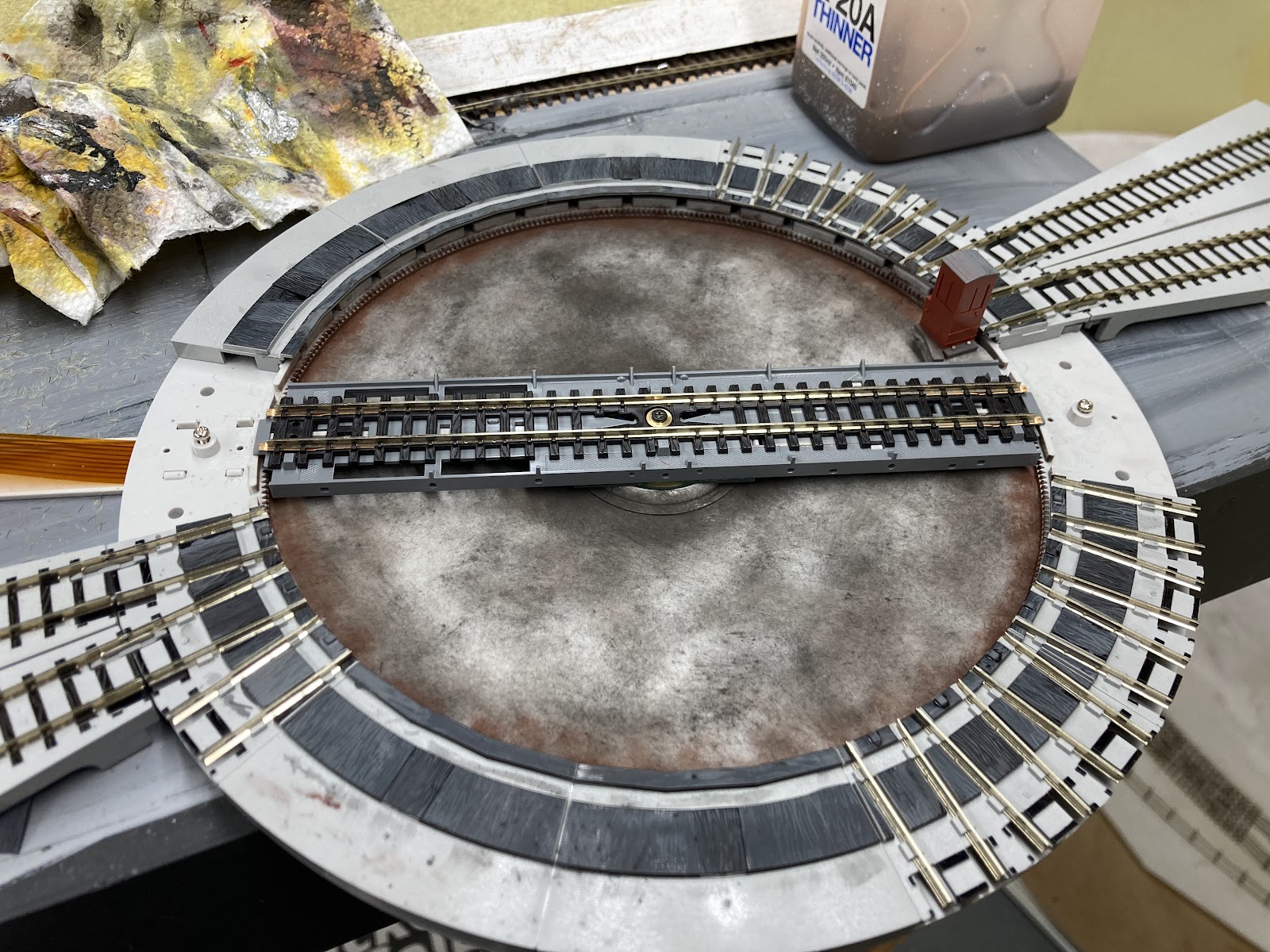
The Kato turntable and DB  Bodgy Track Wiring and Points Control  seems to work pretty well, other than trying to take the DG off onto the little radial track by the foreman's office at 1:30. No go. A quick look under the layout and I've only wired one of the two rails here! D'oh.


So how does it operate?

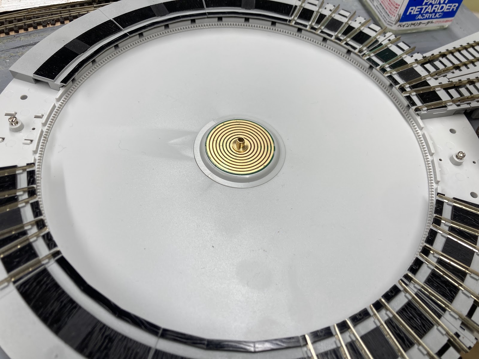
There is a little black switch on the right side of the control box for clockwise', 'anti-clockwise' and 'idle' (centre-off). You move and hold that switch into the required direction, and the turntable unlocks from the current track and starts moving. When you are approaching the track you want the bridge to stop at, you release the direction switch back to centre-off. The turntable keeps going until it latches on the next track. I assume this simply 'releases' the long plastic pin under each end (see previous posts for pics of the disassembled turntable), which pops out of the bridge on a spring like a tortoise's head and locates into the next hole it finds under the track is is approaching. The can motor in the operators cabin probably keeps going until it hits stall current, then switches off.


As for track power routing, there is a feed into the control box that runs out to the turntable bridge. The problem with this is that when the turntable spins 180 degrees, the track polarity obviously needs to be reversed, so the way Kato have implemented this is a silver 'reversing lever' on the control box that you can flip to reverse the polarity to the bridge. 

With DCC this might prove annoying, but the turntable bridge has little copper wipers underneath. These are probably intended to send power into the radial track from the bridge so that the radial tracks are unpowered until you line up with them. However this can work the other way too, so several DCC folks simply don't use any power feed and ignore the reversing lever, simply letting the bridge get power from the radial track it is aligned with. This means you'd need to power your radial tracks, but it also means you need to be careful about their polarities around the circle, and it means that any sound-equipped loco won't get any juice while spinning. This is of no concern to me, as I don't have any NZ120 locos with sound.

The alternative is to use an auto-reverser on the feed to the bridge, and I may do this at some stage to make the thing more bulletproof, although the built-in method seems to work OK so far.

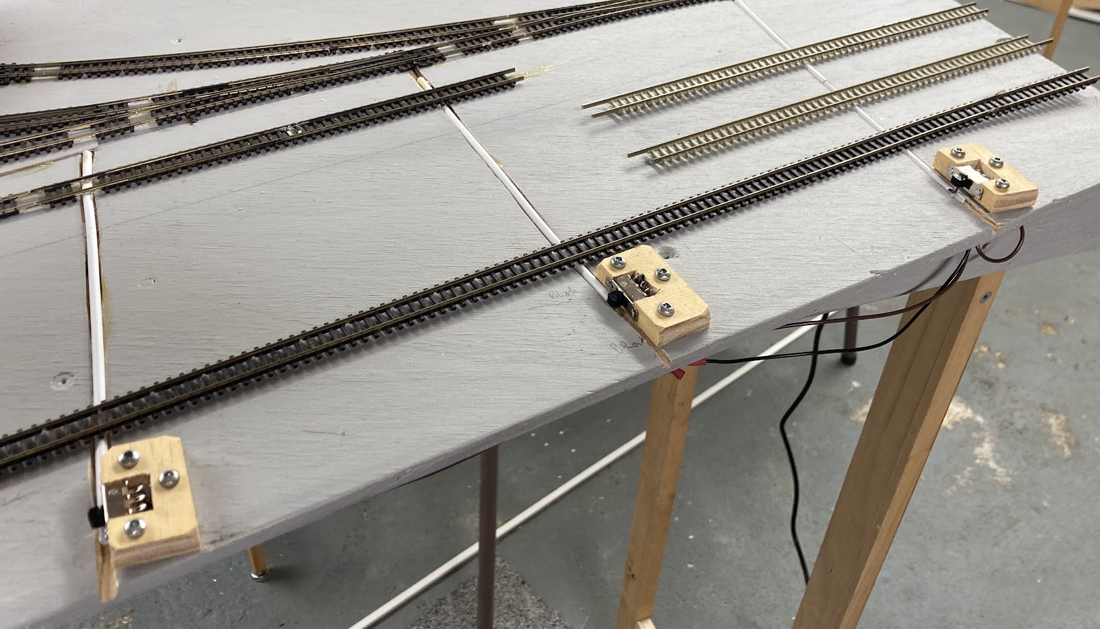
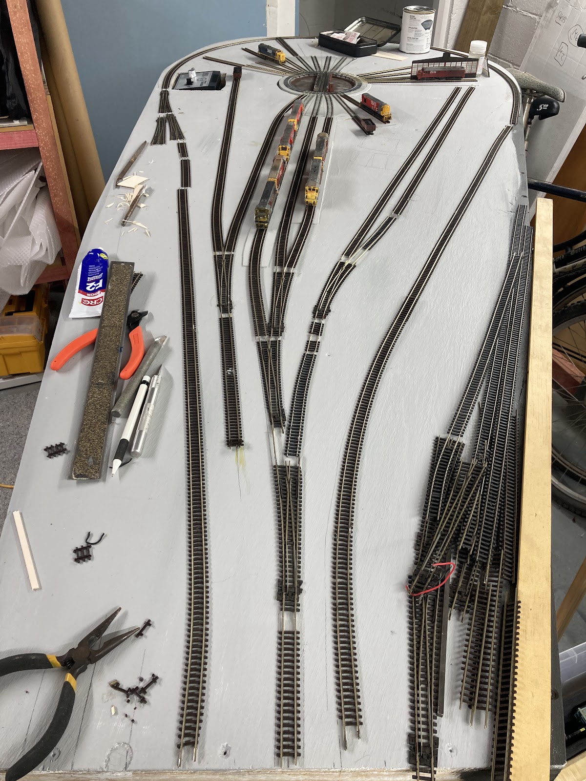
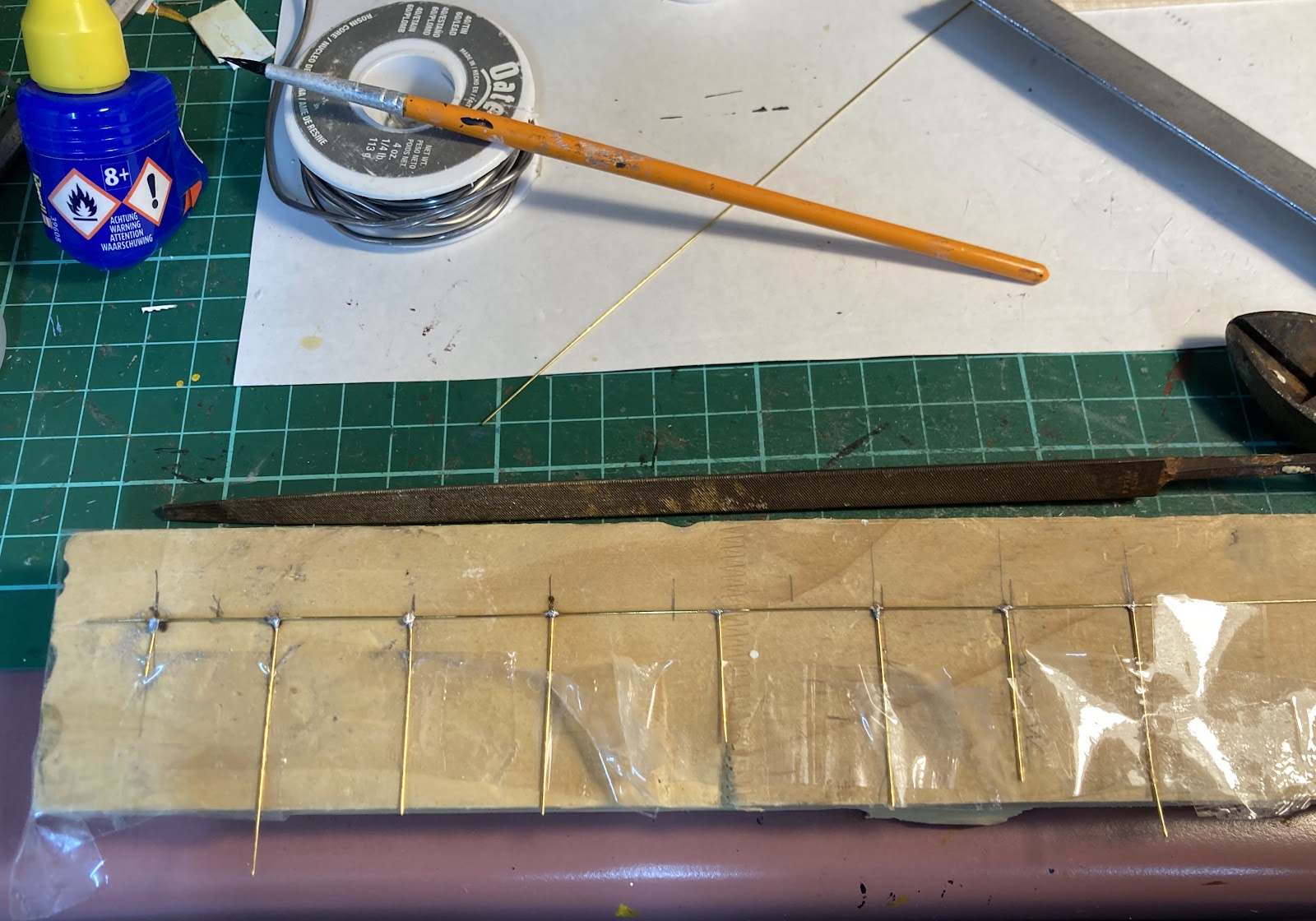
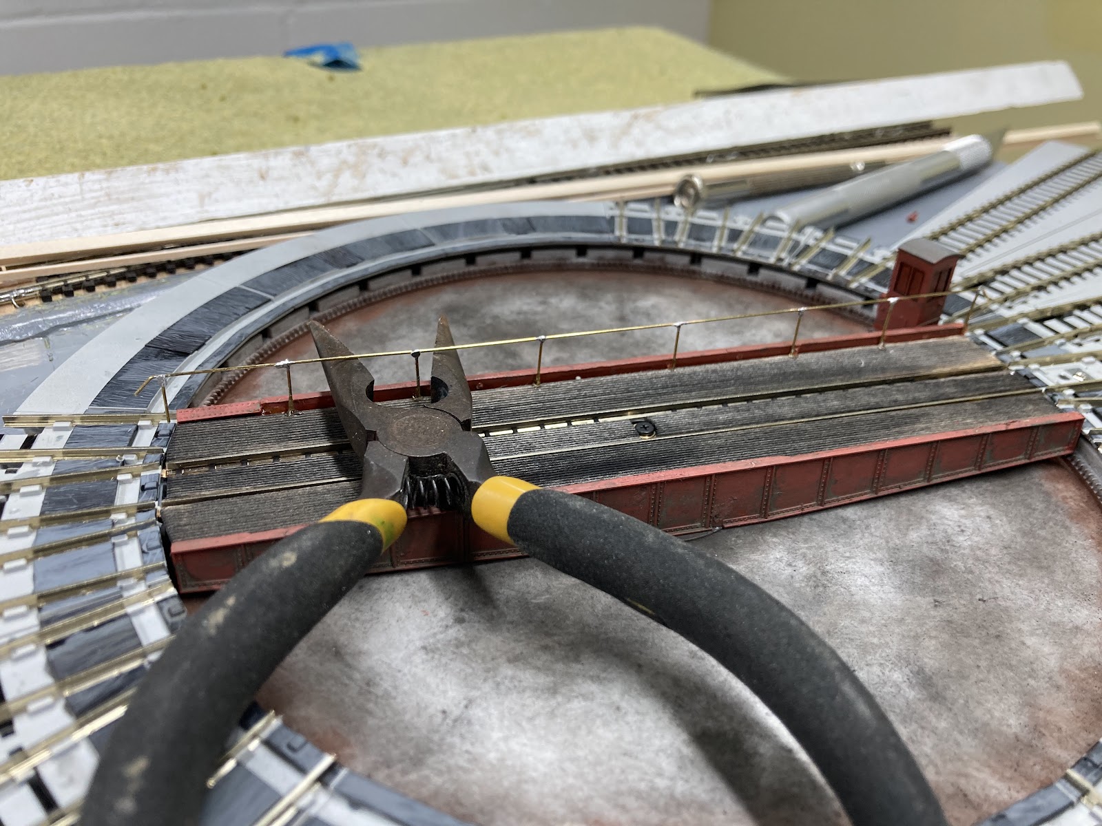
I obviously need to finish laying and wiring up the fan tracks now. 

My first attempt a video ended with a 'buggerit' moment when I ran the DG into a "DCC-friendly" point set the wrong way. Beep beep stall.

I've thought for a while that the real solution to making these completely DCC friendly is to isolate a further "loco-length" section out from the frog, which is only powered when the switch is set for that route. This would prevent a loco from coming into a point set against it. It would still stop, but that wouldn't call the whole DCC system to halt. I suppose this would require a three pole switch.

DCC friendly wired frog:
DCC really friendly with isolated approach tracks:

Tuesday, January 28, 2025

Elmer Lane 9 - Wired.

DB rolls on, since the miserable summer weather continued on Sunday:

The first thing I remembered to do on Sunday was to cut some channels for my overscale point rodding actuators. This was done with a power saw, believe it or not.  With several cardboard boxes as barriers and some plastic sheeting on top of that (and everywhere else) only a few little patches of sawdust had to be vacuumed up.

I then spent a few hours powerfrogging the three points I needed for Elmer Lane, and did the three I needed for Studholme at the same time.

So with that, the rest of the depot trackwork went in pretty quickly. The curved point at the railcar depot will stay as an unmodified Peco.


I didn't have a lot of spare time on Monday and Tuesday, but did manage to solder (my most hated task) a few dozen wires down to power all the depot tracks other than some the roundhouse fan tracks. 

I also needed to route power to the DCC-froged points with a switch that also moves the points with a wire rod. One of the problems I had with Studholme was getting the alignment right so the switch throws the points. It was easy enough cutting holes in foamboard, but I thought cutting rectangles in plywood without upsetting the screw hole for the switch about 1mm away was asking for trouble. 

So I decided to try mounting them sideways in a thin bit of wood. Cut out slot with razor saw, nail in switch (I did this at an angle for some clever reason I can't remember), cut off section of wood, drill holes for mounting screws (so you don't split the wood).


Solder on the three wires, line everything up, and screw it all down. Use those flat headed screws to minimise chances of splitting the wood.


Reasonably tidy, and at least they are completely functional, and they feel oddly ergonomic.


So two part-days of soldering (the most hated task ever) and its ready for testing tomorrow.

The main/balloon hasn't been tackled, but that should be relatively easy. 

Saturday, January 25, 2025

Elmer Lane 8 - Modulus Completeus

 DB Says:

The roundhouse balloon module inches forward in tiny leaps and massive bounds.

The 'wide legs' were attached and a brace added. No matter how many times I do legs, they never end up the right length. 1100 mm, less feet, less module depth etc. Well these were about an inch too short, so I had to go buy some 'long' hinges to extend them. I figured this would be stronger than sticking bits of wood onto the tops of them, and I'd planned to use hinges anyway. 

Looks silly, but its all quite sturdy. As these 'wide' legs are attached to the underside of the module, they obviously fold up snugly against it. as can be seen in the above pic.

The thin legs at the other end are mounted down the endcap, a little closer to the floor, so they fold up a little further from the module, neatly on top of the wide set of legs. Almost as if that's what was intended.

A little tab attached under the middle of the module (below) can hold a screw to keep everything neat and tidy for travel (except for the brace, which I suppose I could attach under the edge to the right of the pic below).


Finally, some primer and paint was added. Dark grey for the 'public edge' (I had a little left over from the Studholme sides) and 'Harvard Grey' everywhere else, because we had an unopened tin of that with no purpose in its life.

And rather than working or watching the cricket on Friday night, I churned out four more end segments before I run out of enthusiasm. Another 2-4 should do.

On Saturday it was time to bring things inside, which was quite easy, and from there, things went somewhat crazy.

It took me about an hour to fettle the holes for the turntable feeders that I'd 'guessed' the locations for into the right sizes and places, but once that was done, the turntable was popped into place, plugged in, and .... it works! Quite cool really. I didn't try powering any locos, but the spinny thing works well. Coolness.

So then the table was screwed into place and the Kato radial tracks glued down. 

As feared/expected, the 6mm ply pit is a tad shallow, so I started applying some (bass?)wood sheet from Mitre 10 that I happened to have handy and that seems to be the perfect depth. This was painted Harvard grey to match the rest of the baseboardA few holes around the turntable and tracks were filled in using this too, to stop the ballast falling through onto the floor. 

The approach tracks were all glued down into place down to where they will meet the points/turnouts at the pointy end. The track that will likely be unpowered that runs down to the turntable control box was also added (with its point, as its unlikely to be powered anyway). As was the first 'main' radial track outside the roundhouse side wall with DG 2376 sitting on it, and two short radial tracks out by the foreman's office (one with the DI, one with an LA wagon of coal for the office). 

I wasn't planning on putting the track in with the DI, but I thought why rip out the little stub that Kato kindly supplied, might as well put a little track in there. Can always not use it...

So that's some serious progress, next steps will be to permanently lay the main balloon track, and DCC those three points at the pointy end for depot track access. Four if I can be bothered doing the curved point where the two railcar shed tracks split. 

Then wiring, soldering some fishplates up, and testing.

Tuesday, January 21, 2025

Elmer Lane 7 - Baseboards (haha)

 DB rolls on:

A few spare moments had me cutting out my bit of plywood into its balloon loop shape, sanding the edges nicely, and checking it does indeed fit into the car (back seats folded down and passenger seat forward).

Hacked holes for the turntable, the kato fan tracks and the turntable control box were then added (removed?!) with a jigsaw, so these items can be installed with their bases below ground level, which should put the rails just above the surface of the ground where they should be, rather than having the whole depot elevated above ground. If that makes any sense.

Overground holes.

Some reinforcing wood ( I believe that is the term that builders use) was stuck on the back of the module. The whole thing is surprisingly stiff. Surprising for something that I have made. I was careful to not have any 'little beams' underneath the turntable, allowing me to put a solid offcut of ply under the pit and most of the fan track cutouts as a solid base for the turntable. A thin bit of dark brown hardboard will hold the turntable control box largely below layout height and inside the loco crew rooms. 

Undernethers pre-endcap at the small end.

The reinforcing beams have holes drilled in them for the inevitable rats nest of wires. Legs have also been made and attached using little hinges. I'm not sure whether the little hinges, even with upgraded screws, are a good idea or not, but they are quick and neat, and in theory they shouldn't be under too much stress. I'm not expecting people to be mud-wrestling on top of the modules. The whole shebang isn't too heavy, although its becoming a little ungainly for this one person to move with any measure of daintiness.

Other than the plywood sheet, all the wood used for the bracing and legs has all come from a big pile of leftover/recycled/offcut wood bits I have in the garage, so things don't always match in terms of material (and some things are 'that size' because that's a handy length of wood I had to hand), but its not that anyone is going to be grading me on my woodwork now that Mr Birch (Form 1 and 2 at school) has passed on to the great woodshop in the sky.

Completed thin end leg attached to end cap, tidy and sturdy.

Wide legs (all the fashion) for additional stability will go under the turntable end.

I have, as unilaterally declared in a previous entry, made this so the rails will sit 1100mm above the floor, and will take 10cm off the Studholme legs to match. 

Aren't standards wonderful! Everyone should have one!

Sunday, January 19, 2025

Elmer Lane 6 - Some Roundhouse End Walls

 DB continues:

As mentioned previously, the printing out of the 'window panes' (an Excel spreadsheet, using the latest technology) onto acetate in my $60 laser printer has been an iterative process. 

My roundhouse segments are a little wider at the far-end-walls than the scaled prototype, because of the Kato Turntable's broader track exit angles. My initial plan, and the first set of 'windows' that I successfully printed a week ago, had the spreadsheet drawn up to look like the prototype in terms of the numbers/sizes of the three casements of panes, and then I added a bit of plain 'wall' either side of the windows to pad things out to the needed 7cm width of each segment end wall. 

The roundhouse side wall (built an episode or two ago), was then made more or less to match those windows in total height, but laid out more or less like the prototype.

Today, comparing my 'padded end wall' printouts with some pictures of the glorious 'wall of glass' that the back of the real Elmer Lane roundhouse was, I decided to redraw the spreadsheet. Damning the prototype plans to rivet-counter hell, I made the back glass 6 panes vertically (to match the sides), and then basically filled the back wall width as much as practical with glass. I think this more closely captures the feel of the real thing. You will probably have seen pictures of steam locos nosed into these end walls. For example on page 27 of Linesider #7, or page 36 of A West Coast Engineman by Ian Tibbles among others.

So after a bit more trial and error, I had a sheet of acetate scaled and printed that looked ok up against the side wall I've already built. As with the side windows, this was Dullcoted on the inside (opposite the laser printed squares which are on the outside.)

From the previous session, I had enough leftover painted 'corrugated' bits already cut to the right height, so cut out four back wall segments out of the acetate sheet to make up. 

For the bit 'above the windows', which on the real thing is also made from the corrugated material, but on the model will be almost completely hidden under the eaves of the roof, I just used the dark stained stripwood rectangle pieces, again contact glued on to the acetate wall. 

Then the corrugated pieces were glued on the bottom, all with Ados F2 contact cement, the choice of a precision new generation of modelling neanderthals. And it smells good. 

I let this set for a generous two or three minutes before flipping the walls over and adding vertical 'beam' pieces on the edges of the interior out of the smallest (maybe 1.5 or 2mm square) stripwood that had been pre-darkened. I wondered if this would be enough to keep the windows flat or whether I'd have to add two extra pieces of strip in the middle to stop the windows bowing, but they seem OK at the moment.

These were also weighted down. Then it was simply a case of adding the window sill and the vertical bits out of red-painted plastic strip, which I almost immediately ran out of and had to paint more and hang it to dry mid-session. 


I reckon this don't look too bad, and with the acetate segments guiding my way, it didn't take long to make them up. When its assembled for good, I will put a 'filler' bit of red plasticard strip in over the top of the window join, as mocked up over the top-right join below (it will be cut to size):


I've blacked the edges of the corrugated stuff and stripwood with a Sharpie, so I'm hoping I won't have to fill those joins at all when the walls come together, but we shall see. I'll have to modify some of the reinforcing stripwood by bevelling a bit off at the join between the side wall and the first end wall so they mate up nice and close.

So that's four segment walls done in a couple of hours, and I have another 8 or so cut out of acetate. If I have a total of 15 or 16 segments in the roundhouse, I probably only need to make up another 6-8 of these as the rest will be 'around the back' away from prying eyes. Plus there were three 'workshop extension' segments on the prototype plus one that had a door, so these could all just be solid wall. We shall see as it comes together. 

Tuesday, January 14, 2025

Elmer Lane 5 - NZR-ising the Kato Turntable

 DB continues:

So the Kato Turntable isn't very NZR-like out of the box.

As mentioned previously, "it does have a shallow pit (yay), however the bridge girders are 'upside down' compared to NZ turntables (boo), but surely the sides can be flipped to look a little better? Its modelled on an electric one with a gantry in the middle, but I'm sure that can be removed, and there is a little red operators cabin at one end. The bridge length is a smidge short, as we are 1:120 and Japan is usually 1:150 rather than the usual N 1:160, but its not actually a million miles out. In fact according to my calculations it should fit a scaled down Ja wheelbase. "

Well, lets do some more digging.

As predicted, the central brown gantry was an optional part that I simply didn't install. The brown main girder sides (made of an unusual tough but flexible plastic) can also be gently prised out of the bridge (a press fit).

Similarly the operators  cabin can also be gently levered off, and .... surprise(/whoops)... there is unexpectedly a tiny vertical can motor in there which is how the turntable is driven! Nifty, but that means the cabin needs to stay. Good job I was more careful than usual with the removal of this or else I'd have buggered the whole thing. I suppose this could be replaced with a new drive mechanism underneath the pit somehow, but that is well beyond the scope of this wee project.

Underside: electrical wipers that control the bridge's turning, the track power, and the operation of the little prodders at the ends of the underside which mate into holes under each road for positive location. Clever stuff:

The power feeder 'LP' below and the positive location locking rectangular holes can be seen under each track position, above the toothed rail that runs around the outside of the pit.

The first thing to be attacked while "the bridge was out" as the Dukes of Hazzard used to like saying, was to weather up the pit.  I could have ballasted this if I wasn't going to have the turntable bridge girders hanging down as low as I can get them. My efforts were done with some thin dappled drybrushing and chalks. It looks a bit hokey and contrastry in these pics.

The operators cabin has been minimised at its backside, weathered, and the roof painted grey. The girders were thinned to clear the power feed LP, painted a similar colour as used on the Elmer Lane roundhouse window frames, and glued on. Dark weathered scribed stripwood 'walkways' were then added on top of the bridge:

OK, not 100% convincing, and the DBR makes the bridge look pretty small, but not bad for an afternoon's effort.

Next morning I put aside my irrational fear of soldering things to other things and made up some handrails. I got better as I went along: plenty enough flux, minimal solder.


These were installed, and the pliers above are holding one end up of the first attempt (with its solder blobs) at a good height while the glue sets. 

It was then painted - white along the top rail and grey for the supports. This looked a bit overbling, so I made the top handrail grey too except for the ends. I'm not sure health and safety had been invented in the late 1960s anyway. But then nor had TMS numbers or DBRs.


OK, this was never going to become a 'real NZR turntable'. Its a bit small and it has an operators cabin at one end that can't be disposed of. It is a girder type, and although most of our bridges were cast ones with big holes in them, Elmer Lane did actually have a plate girder fabricated type like this one. 

This is also a 'through' type of bridge, whereas our structural parts of the turntable bridge were typically much closer together,  sitting under the rails, with the non-structural walkways cantilevered out from the sides.  Due to the location of the operating mechanisms under and on the bridge, plus that filigree LP power pickup, the Kato bridge can't be thinned easily. Its not something I'd want to hack at. 

Its also just occurred to me that I haven't put any power into it to see if it works. It probably doesn't now!

Saturday, January 11, 2025

Elmer Lane 4 - Roundhouse wall

 DB just couldn't resist...

The Elmer Lane roundhouse was pretty cool, alas I only got to see it in its truncated 4-stall edition in the early 80s. Despite owning no steam locos, my Elmer Lane will be late 60s at the turntable end (full roundhouse, sand tower, water vat, light-up wood etc),  and diesel focused at the arrival end (plain sidings to park pairs of locos). 

The roundhouse is obviously the first thing to tackle, especially as I was looking at the site of the real thing on Thursday.

I picked up a few sheets of A4 acetate overhead projector film recently and started playing in Excel, forming some 4x8 panes, using 'double outlines' on each cell. These were copied and pasted along and scaled by trial and error (printing on ordinary paper). When I had these about the right size they were printed out on the acetate. 

My plan below is a little underscale, maybe an inch or so short in horizontal length, but I need to build a little tall, as the locos still have to fit through the doors! I will hide the bottom 5mm with ballast.

I did the same excel/acetate thing for the back walls, although with the Kato turntable legs splayed a little wider than the real thing, each of my wall segments will be a little wider. 


Here is the printout with some indicative side shapes drawn in with a fine marker.


Stripwood was procured from Mitre 10 in various sizes for supports. Some was painted/stained dark grey and some strip plastic for the window frames painted a reddy-brown shade. These were hung out to dry.

After spraying a reject printout with Dullcote once on the front and once on the back as a test, I decided spraying the backside/inside was better, this provides a slightly opaque/dirty look to the windows, but leaves the laser printed panes on the outside. 


The real roundhouse had corrugated metal on the sides and rear walls with massive metal casement windows. The curved side facing the turntable was wood, and the roof a malthoidy thing. 

I have some corrugated plasticard, a little coarse, bit it will do. Oddly it was prepainted the right shade of browny black, I think from some containers may moons ago. A windowsill of my painted stripwood was added on top.

This was glued on successfully with a big honkin tube of Ados contact glue. being careful not to get any on the window glass. Interior beams will provide stiffening, so these were cut to length: 


And glued to the inside:


Additional reinforcing top and bottom on the inside:


Prepainted reddy strip window framing adorns the outside, very carefully glued, hiding the beams:

And the top corrugated piece added:


The top black bit looks a little tall above the windows in the above pic compared to the protype picture from "Steam Inclined", but there is a fairly deep roof fascia that will hang down and cover this, and as mentioned the lower 5mm will be hidden in ballast.

Monday, January 06, 2025

Elmer Lane 3 - real word curve testing

 DB continues:

So, Elmer Lane, with a more-than-180-degree balloon loop, all able to be squeezed into a car... Well the whole turntable and roundhouse thing wouldn't work very split down the middle across two modules... but is it practical? There's only one way to find out.

Lengths of second hand Peco code 55 flex were unearthed and the soldering iron fired up. It only took one joint at the head of the curve, the other pieces of straight flex were just fishplated in. The curve had four or five staples applied to keep it tight

Then the Digitrax DCC was dug up, it took me a few minutes to remember how it all worked, but soon enough, some of my DCC locos had what might be their first real spin in about 13 years. 

First up was the challenging test train: a light 1990-built LC up front with a glued-stuck Microtrains coupler (connected to a long body-mounted DX coupler that will want to throw out on the curve), some lightweight four wheel and bogie wagons (all with fine flanges), including a KP with a loose weight rolling around inside it, the light and long GT car carrier, my new flat UK and the featherweight laser cut plastic ZH, and then at the back, heavyweights and top heavy wagons - resin castings and the new Trackgang Zs and old CF. This pic taken just before coupling up for the first run.

And... no drama to report at all, except I could only get one of my DXs running at first, so it had to take the train, alone and slowly. Success! 

Then when trying to push it back around, a stall, with the middle of the train in the middle of the curve, and the DX's wheels spinning. But no derailments. I knew this floor wasn't level,  but I didn't realise quite how much. Some books were employed to lift one corner a bit, but to no avail, the mighty DX was beaten on the uphills.

The day was saved by DG 2376, on a heavy Kato PA-1 chassis. Man that thing can haul. Up and down no problems. It was only when packing away the train it was found that my GT has a splayed bogie, so the one wheelset that was left on the track when I picked it up probably wasn't rolling at all. 

After this, it seemed like a good opportunity to play trains. something I don't do enough of.

Here's the single DG on a coallie. The heavy CBs are in the middle (they have pizza cutters which rub on the metal wagon floors), and an even heavier Trackgang CF is at the back of the lightweight CWs. No dramas pulling or pushing uphill at quite decent speeds. This train looked nice behind the two KiwiRail DXs when I got the pair running and multiple-united together, although they run slow.

Not entirely prototypical, maybe the DG should be blue

The TranzAlpine then came out, and this is a pretty heavy train with a high centre of gravity as the cars are solid resin, but they have nice metal wheelsets, so I had no qualms with the DG and later the faster DFT pushing this uphill around the curve at unrealistically high speeds. 

So the verdict is that even my creakiest old wagons in a worst-case consist seem to run fine around this sharpish curve. And so they should really, this is flextrack laid out in a smooth, flat circle with a single soldered join, and an 18 inch/450mm radius curve isn't crazy tight. With a more sensibly-ordered train (heavies at the front, free-rollers at the back), I can't see this curve being a problem unless there is way too much speed and herky jerky operator error.

More worrying was that many of my locos didn't work, or took a while to get working, or barely worked at all.

A few may have an incorrect address programmed on the decoder for some reason, such as DG 2330 and DJ 3067, both of which were DCC-ised not long before all this stuff was packed away. I didn't think to get out a programming track to see.

None of the Atlas SD35 chassis under the Da/DBR/DCs worked well. Cleaning and better electrical connections between the decoder and metal split frames are required, although I did have DC 4559 and 7132 (both blue) on the Tranz for a while. 

DF 6277 and DX 5448 ran jerkily, and DF 6064 could barely turn its motor with lots of humming, so something must be binding in there. These are all old Kato chassis with decoders that were hardwired in 1995 for my little 'Wellington' layout, built after I purchased the Digitrax. Amazing to have an electronic anything that still works after 30 years and will even drive modern decoders.

The two KiwiRail DXs on Atlas Dash 8 chassis with clip-in decoders are nice and smooth, but must have their VMax set quite low, perhaps to run with slower locos? Their maximum speed at 100% is preeeetty slow. That should be fixable easily.  

The stars of the show were undoubtedly DFT 7132 and DG 2376. And the curve. 

.....

However, I don't want to get too distracted by this until I have finished the hard work of Studholme...