Friday, April 30, 2010
Even Fuglier
While cleaning up one of the spare rooms I came across a first edition copy of Ken Cassells "The Sanson Tramway" that I'd squirreled away many years previously. Its a nice wee read, not too taxing, quite pleasant in a way....until you reach page 64:
"...the frames of a "Wa" class 2-6-2 tank locomotive lying at Gisborne were purchased from the NZR and on these was mounted a Holt petrol engine from an old tractor. To the motor was fitted a gas producer, as a fuel economy measure, and a drive was taken through a gearbox, made by A. & G. Price Ltd of Thames, on to a pair of six coupled wheels from one of the old Fairlies. Over all was placed a housing of the "steeple-cab" type, fabricated in the County workshops out of welded steel plate."
The author does wonder about including streamlining on a locomotive designed to run on a line with a speed limit of 12mph, and apparently it drank a gallon of petrol every 200 yards! Apparently it was modified and ended its days in Westland, probably on some out of the way log tramway where it couldn't offend the sensibilities of townsfolk.
So there you have it...possibly New Zealand's ugliest locomotive. To me it looks like a beagle...maybe a two headed beagle....It does raise the question "At what point in the design phase did they think this would be stylish?"
Thursday, April 29, 2010
Freelance
The main problem that we have in this country is A) its too small and hence well known (and B) ll the railways that have been built have made sense to some extent, and theres not many areas (bar Nelson) that don't have a railway that should have one. I have seen an S scale layout based on the premise of a second route to the west coast up another valley further south (which on a map made sense but I can't remember where it was) with a tunnel etc. I think you would be OK modeling a branchline somewhere (gawd knows enough of them were lifted), but somewhere with enough traffic to sustain a modern day line (which seems to be the period of choice for the masses out there at the moment).
Maybe/probably the other problem is me. I can manage cut down real locations to fit smaller spaces but I still struggle to make up a station. Even renaming a station would feel odd to me for some reason, possibly cos I know its not right which then bugs the hell out of me.
Wednesday, April 28, 2010
Its Made my Day...
Its been a bit difficult recently to get enthused about things trains. All I seem to be doing is spending a lot of time reading through datasheets and plotting axle lengths against different manufacturers wheelsets....Which will lead to great things when its done, but is all a tad tedious at the moment.
So I was exceptionally heartened to read Graham replying to another post with "I have also had a go at making a J5 from the nz120 site in styrene cut on my cutter at home, looks ok but no engraved planks on the first one."
Congratulations Graham for taking the plunge...you could well be the first user of an open source wagon plan in New Zealand (unless there are others who have kept it quiet, but thats not the point, is it now boys and girls).....and it makes me feel like my endeavours werent all a waste after all.
Sigh..I'm feeling all squiffy now...(but that might have been the onions)
Tuesday, April 27, 2010
A sows ear out of a silk purse
(*Well, I guess what your definition of fancy tools is. A week ago I would have said a fret saw is a fancy tool but since I've now had one donated to the cause, it no longer is. If anyone has a spare lathe going free, just drop me a line)
First up, cut a piece of rail (code 55) to length (about 30mm in this case).
Now, take your fret saw and cut through the rail until you have cut far enough through the top and the foot (the top bit and the bottom bit) that you can see a line on the other side of the web (the middle bit). you don't have to go through, as the line indicates you are deforming the metal so its very thin. If you cut too far, just start again.
The next step is to establish the angle of the frog. For this part unfortunately you need to know where your track center lines are. Transfer these onto a piece of tracing paper. In this example I have marked out the straight and curved lines directly from the point, and then transposed the curved line onto the straight line so that a 'X' is formed
CAREFULLY bend the rail to fit this X. Break it, and you will be set back a whole 2 minutes.
Then move the bent rail to the vice, and position it so that you can merrily file until you get to the point where you are down to the same level as your initial saw cut.
Taking it out of the vice you can see how we have filed out the inside.
Then carefully bend the rail back on itself using the first cut that you made as the center point of the fold
And the end result.
Normally you would do the finally soldering in situ to get the correct angle , but in this case I've just done it as a demonstration to show that its actually fairly easy, and you don't need a fully equipped workshop or a stack of skills.
Monday, April 26, 2010
Thinking big
When we chose to build a layout we tend to pick an area that we would like to model based on the types of train running, the location or area itself, or because of a family attachment to the area (or a mix of all 3). Therefor to model that particular area we then choose scenes that indicate where it is in the country (west coast bush, rolling hills, plains etc). The problem for me then becomes that by altering other things to do with the area it then becomes not quite correct as a model. Maybe its a problem that I have, or maybe I just get tired of smart arsed comments from other people which really hose me off for some odd reason (odd because I'm normally thicker skinned than that).
Taking one of the examples from yesterday. I really like the Greymouth waterfront, but I don't like how a layout would turn out with the main station. then there's the Cobden bridge which means that you could model the railway up to Rapahoe/Rewanui (which has pitfalls of its own being such a famous site). (Actually, I think I might have just cracked a way of doing this, so I'll have a bit of a rethink on the whole thing)
Likewise the Southland branchlines. I like the triangular layout of the Invercargil/Gorre/Lumsden arrangement, with short branchlines off every leg, plus the line up to Kingston. however to model something like this would be a massive undertaking and require a large area.
Another Area I had considered was the Wellington suburban area. if modelled in 1954/55 you could have the electrics with the last vestige of steam still running. at that time every second station had a yard, then there would be the added attraction of the run up to summit which would mean that you would then have to model Cross Creek as well. throw in the J'ville line and of course Paikakariki (which is a great end station from either direction).
This is starting to think quite big isn't it....
Sunday, April 25, 2010
Sunday morning
Likewise with a Southland branchlines layout. A meandering collection of lines with a wide variety of traffic which would be quite cool. To have an operating layout with all these included might be a bit difficult as there was only one large loco depot at Invercargill, and you would need quite a large collection of locos to run it. To get the mainline trains you would need to model the main line towards Gore.
For a more modern theme, the milk trains runing in Taranaki could be interesting (you can't tell if they are loaded or unloaded), but I don't have enough information to decide if it would make an interesting layout. Finally the Auckland surburban scene again is something i think that could really work in an operational layout. (I keep thinking if Wellington would, but I'm not sure).
I'm not quite sure what my ramble has achieved here, but hopefully I'll be able to add some more later in the week.
Saturday, April 24, 2010
Trackwork pt III
(why do I feel like I've just written a passage in Greek? I promise to do this properly with pictures when I get everything sorted a bit better)
Finally after all this was done, and everything installed, in went the check rails. these required a bit of tweaking to get right as there was a fair bit of lateral shifting at the wagons rolled through.
Amazingly after all the buggering around, it works. Now I just have to gap the PCB sleepers and then install the tiebars and that's it. My first piece of hand laid track, an exact fit for the location, all for the princely sum of about $15.
Hmm, now which bit is next....
(Oh, and as a note of interest, the newer Peco wagon wheels (the spoked ones) are NMRA compliant, where as the older solid ones are not. The Parkside Dundas ones are rather 'variable' but can be adjusted, though the metal rims do have a habit of popping off the plastic inners. They are just a press fit so its easy to fix)
Friday, April 23, 2010
Trackwork pt II
This unfortunately had the consequence of placing the gap in the frog over a sleeper, thereby negating the gap. I also wasn't happy with the length of the frogs, as I think that they might need to be longer. This then prompted an unsoldering and refiling of various bits of track. Progress was steady until the fret saw decided to de-fret itself as the blade broke with a rather sad little plink.
This had other consequences to the point (haha) where I'll need to have a bit of think about the whole way it goes together. Having made a few mistakes in the last couple of days i think I've got a better grip on what needs to be done.
I will say however that what works quite well in S scale, doesn't quite port down to TT with its reduced clearances. Interestingly enough on this topic, The previous point that I made (crap that it was) which will allow Peco wheel sets through just by butting the rail webs together before soldering, is actually narrower than the NMRA track check rail spacing (at 0.7mm on the metal gauge).
As a final shot, here a van on the bit of track that is finished for the moment.
Thursday, April 22, 2010
Public Service Announcement (Pt II)
For those of you looking to make use of the J5 drawings available over at Nz120.org, Airsail in Auckland stock 0.4mm Birch Ply for $30 for a 300 x 300 sheet. Sure, that works out at over a few dollars a square centimeter, but if you only want a few I'm picking you dont want to spend over $200 for a 1200x 1200 sheet that then kills you for freight to move it to where you live.
The list of available Ply on the Airsail website is here.
(This is one of the few posts I've done without pictures...feels wrong, sort of....)
Wednesday, April 21, 2010
Trackwork ptI
As you can see if you expand the picture, the pencil mark is in the middle of the 7 sleepers. The frog is well behind that, and is correctly positioned according to the NMRA track gauge. Bugger. I've had to add another sleeper behind it so that I can solder the next piece of rail on behind it. Must check the measurement on the other point.
Next post I'll also describe the method of making the point frogs. Its actually very easy, takes about 10 minutes, and seems to be almost foolproof (last night we just discovered someone had invented a better fool, who I see in the mirror every day)
Having said that, its getting oddly addictive, and I'm looking forward to getting a bit more done late tonight.
Tuesday, April 20, 2010
Happy birthday to us
Well, its been another year of very interesting bit, moderately interesting bits, amusing bits, and the remains any of the drek I've typed. I'd like to think we have rivaled the local rag in breadth of topics (thought we have yet to touch on anything before about 1950, so maybe they have that market sewn up).
On thing I have noticed looking back at some of the early stuff I wrote is how much the blog has mellowed in the past 12 months in its opinions and viewpoints. Maybe its something to do with the increased readership and the remote possibility we might hose someone off. Maybe not.
I'd again like to that my fellow contributors for their contributions and useful alternative counterpoints to my daftness. Hopefully we can carry on producing whatever it is we write in the next 12 months, and start converting some heathen S scale modelers to the small um dark side. There is no point trying to lure the 9mm guys, they have decided which side of the detail/landscape side of the fence. Its the ones still on the fence we can get.
(Yes, you, I'm talking to you in the back there skulking behind that optivisor trying to quarter his drivers, who doesn't have a large shed or a hankering for 1950's steam engines. Who would just like to build a small layout and run some nice modern diesels on it. Come on, you know you want to. It won't hurt....much)
Monday, April 19, 2010
In Limbo
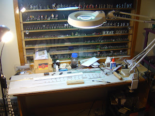
This was going to be a discussion about how I am making my first piece of track (the crossover by the electric loco sidings). Unfortunately we have hit a problem; The lady of the house has an aversion to metal filing in earshot, and refuses to move out to the garage.
Thus work will have to be on a go slow (after she has gone to bed) until later in the week when I have some time alone.
I'll also point out that no, my eyesight has not packed up, the light/magnification device is 'borrowed' from work to test its properties. My early thoughts are that there are some things I really just don't want to know about, and the rest of the time it just seems to get in the way.
I'll give it a few more weeks, but I think it will be heading back to work for someone else to acquire.
Sunday, April 18, 2010
Saturday, April 17, 2010
On tour pt IV; other stuff
The Craven steam crane at Paekakariki (minus its cab and boiler). This is a prototype that cries out to be modeled in kit form in any scale. there would be a fair bit of work to be done getting the crane part to look good, mostly brass etching i think. there were pictures of a scratchbuilt 9mm model in the journal donkeys years ago which was fully operational from its own separate controller.
Point at Pahiatua. Note the 3 cross braces on the point blades. These don't tend to be modeled in the larger scales, and they would have to be in something non metallic to prevent shorting.
And finally the iconic;
Friday, April 16, 2010
Friday night public service anouncement
I was wandering round Warehouse stationary today and came across this.
Its an A4 non cuttable board that comes with a knife and a couple of blades (the odd shape is just the packaging), all for the princely sum (on sale but you have to ask) of $3.60. They had larger cutting pads but I don't have the workspace to use one.
The sale ends Sunday.
(there were not many left when I was in Nelson today, so locals might be out of luck)
On Tour pt III: really out into the back blocks
Heres another W11 insulated van. they seem to be rather common, but I've not yet seen one restored.
Ok, so you don't want to see wagons, Pahiatua is famous for having the last remaining twinset railcar bits in the world.
As you can see, these ones are not in crash hot condition, but I think that the main project is inside the shed, which I couldn't get into (and I would have loved to have seen the wairarapa car in there). I took sme more pictures, but none of the underframe, so sorry to all those who were dying to model an Ac 'grass grub' (I guess you will all just have to die a little more).
A nice detail shot of the bogie, without brake cylinders.
Finally, heres the odd beast that they use to shunt the yard. Its an odd wee beasty that some kind reader will be able to give us some more info on.
Thursday, April 15, 2010
Hints and tips time.
Anyhoo, today I'm having a closer look at the assembly of the laser cut J sheep wagon, as its not an easy prospect. Since I've assembled 2 now I'm appointing myself the world expert until someone else does 3 :v).
First up this time around I decided to paint as I went as some areas are impossible to paint after assembly. The first tricky job is to place the horizontal slats in place. this is easy enough using a door as the template. However, what it doesn't day in the current set of instructions is anything about the horizontal position.
(sorry about the pictures, I had plenty of light, but the camera didn't seem to think so)
As you can see here (sort of), the planking should sit level with the outside of the last upright post, with no overlap. The inside end piece will eventually slot in here.
Here I've painted and weathered the floor by drybrushing with my Iraqi sand colour (and a dust with a wee bit of white to cap it off). I wasn't happy with the first one in that I couldn't get into the crevasses that appear when the cross beams are added.
Now we move to the hardest bit of the whole thing (putting the wires in are a doddle compared to this) the easiest way I've found to do this is as follows
First join the 2 ends to a side as it says in the instructions. They don't have to be particularly square at the moment, just well glued.
Next we glue in the inner ends, making sure that the details are facing outwards. These should fit into the slots we left earlier...
Adding the floors is the most fiddly bit. I start of by gluing the lower floor ( the one without the slat detail) into position just by applying PVA to the indentations on the sides. DO NOT attempt to glue the ends to the floor as it could really bit you in the butt later, leading to contributions the the swear jar and disapproving looks from the local vicar. The floor should sit down on the bottom horizontal frame post.
The floor can just sit hanging down a bit. PVA is reasonably flexible for an hour or so after it 'sticks' but before it 'sets'
The upper floor can now be fitted in, again just gluing the indentations into the side posts. let it set a bit while standing in vertical.
The second side is then fitted into place. you don't need 4 arms, just a sharpish tool to maneuver everything into place until it clicks in. Again just apply glue into the indentations on the sides of the floors.
And there you have it, a semi complete wagon only requiring doors and bracing to complete it (oh, and a chassis as well...)
Finally, here is a line up of the various attempts to model J sheep wagons.
The first one is a resin cast version that I made 20 years ago. This was quite impressive for its time casting wise, but somehow muggins got the dimensions wrong and it was too big. The second is the Mk II version features a few months back, with some detail to be added (and the doors corrected). Finally we have the finished product, which scaled up would not look out of place on an S scale layout.
Wednesday, April 14, 2010
On Tour pt II; wandering the back blocks
Anyway, among other things I was hoping to get some pictures of Ka 945, but since the shed wasn't open, I had a look round the site, and struck gold. You see the biggest problem when getting shots for modeling is that there is often lots of stuff that's in the way. However if someone has already striped things down, the problem goes away.
Leading or trailing driver, possibly for a Ja.
Take the tender out of the way, and voila, the bogie is exposed.
I can now finally work out just how the whole thing actually goes together, which 2D paper plans just done explain very well.
Want to see the cross head guide bars and valve gear hangers? just take all those annoying rods off. Why not remove the cylinders as well while you are at it?
A surprise for me in that the guide bars are not connected to the cylinders, and also note how far the main drivers crankpin sticks out from the wheel.
And we may as well get a shot looking the other way as well.
What do the front frames look like behind that metalwork at the front? A bit hacked around a bit, buts still visible.
Finally, there was some discussion on the standards thread at Nz120.org the other day about the possibility of having a dead scale wheel standard. as you can see from this stack the flanges are very small (which back up my measurements on local wagons)
Tuesday, April 13, 2010
Gorgeous 2: Dropping back
Life seems so busy these days it's hard to find time for fuddling around playing trains, but nonetheless, here we can see that the backdrop is up and setting.
In a comment to my previous post, Michael A suggested toothpicks for holding foam in place while it sets. (FredDagg voice) "That's not a bad idea..."
As I'm using fairly thick foam (about 7cm thick for the base and 3cm for the backdrop), I used BBQ skewers instead, some cut in half and sharpened with the knife. Excellent suggestion. I have a few of these in the train room and normally employ them for stirring and extracting model paint from tinlets, potlets and botlets.
You may note that I have also installed a coved corner in the corner (well where else really) using some .020 styrene sheet. This time its in 'landscape' orientation to give a larger radius to the curve. Its held in place using magic and 4 pins while it sets. Well little bits of fine brass wire as I couldn't find any pins. Or magic.
So things are coming along, and hopefully I'll have some paint lashed on it before my next post.
[postscript: you can't load pictures into the blog from your iphone so don't bother getting one]
Monday, April 12, 2010
On tour pt I
A couple of shots first. this is the south end of the station looking towards Wellington. This area will be the scenic break atthe Wellington end of the layout, and its quite well set up, with some big trees on the left and a double story building on the right. No 'vanishing into a hole in a bit of wood' for me, matey!
Looking the other way towards the engine shed. A closer inspection of the trackage reveals that most of it in the loco depot area has been relaid. Also a nice view of the Airrail shed and the relay building. As a final note, observe how steep the hillside behind is.
Looking back towards the station. Relay box again in the middle of the picture. the bolier on the left is one of the Wb ones I think.
Back down by the loco shed, the hillside on the other side of the track. again a good scenic block for this end of the layout.
70' Turntable. This at least is still in the same place, but the tracks have again been modified. however you can still make out where they were.
Finally the two water vats on site. Both to the same design. I think taht there was only ever one on site, but I could be wrong.
I also got a stack of other more detailed photos of various bits and pieces, but some are really not interesting at all.
Sunday, April 11, 2010
Why I does what I do....
On a previous comments board, ECMT opined:
"I still reckon to do away with free file downloads. It's a great thing that some guys have done in allowing the files to be downloaded, but where is the appreciation for it ?"
So why have I loaded up some files for free download to all and sundry? I dont think I really know...but this is as close as I could get after some self analysis:
- I want to be able to say " I dont care about the money, its all about the scale, stupid!". And I want people to share that value.
- I want to fight back at the greediness apparent in some other scales in regards to pricing. Obviously I'm not talking about Russell and Trackgang (loving your work, Russell!) but when I was modelling in that other scale it worried me the prices people were paying for stuff that wasnt even very good! Sure, there are some really nice kits out there and I would gladly pay for quality. Others I'm horrified with....
- I want to encourage people to make things. And despite all the protestations I keep hearing, Brass is not the way to introduce people to the hobby. Although you may be able to solder gnats whiskers to a mosquito probiscus with no overrun, soldering scares the bejesus out of the rest of humanity. Give them a plastic or wood kit to get them started, then move them gently onto brass when they are ready.
- I want to encourage people to start becoming producers themselves. That way, we all benefit. If someone can look at my drawings and use them as a basis for their own work, even better. Annoyed that something isnt available? Produce it yourself! Odds are others are annoyed as well, and you'll learn something to boot (The actual price of production if nothing else).
- Again, following on from the above, I want our scale to more resemble a Bazaar (with lots of communication, selling, buying, co-operation and haggling) rather than a Cathedral (where those up the front tell us in the pews the rules that we must follow).
- And yes, I probably did it for a little vanity as well (And there aint nothing wrong with that).
Will there be more drawings released? Probably. Cant say when, but probably.
Saturday, April 10, 2010
What you are missing
Assembly of the wooden components was done entirely with PVA
First up I decided to tackle the upper floor. This has braces running across (which are the long thin bits of wood). There are gaps rastered onto the floor to show you where to place them. One of these in the middle has the gaps in the wrong place, but just make sure that they all look the same and it will look fine.
after the glue has dried, cut of the excess and glue them into the gaps that are left.At this point I would paint and weather the floor as its hard to get at them after it is assembled.
There is a bit of a photographic gap here as I got stuck in and assembled everything rather than pausing. Sorry, next time I'll do better. I followed the instructions and managed to get everything together. When the next batch arrive I'll see if I can come up with a better way of doing it. The floors want to rest on the horizontal side beams and I see no reason not to let let them. Paint as you go, and after the sides, ends and floors are all together you can add the mylar strapping. I used tiny amounts of contact adhesive in the corners and centers to hold it down. Cut a tiny bit of the lower strapping right next to the door so that the door runner won't sit proud on it. Again everything is painted as you go.
The sides have slots rastered into them to aid in the fitting of the wire. this should be as thin as you can find. I had some fine stranded copper wire which did the job. I think hair from a short haired cat would do just as well.
With the doors you are not quite so lucky, and have to do it by eye. however I start with the center wire placed 1/2 way (mk 1 eyeball works fine) and the the other 2 in 1/2 way between the center wire and the edge. Again I used PVA to do this, with a coat over the top. after the glue dries, turn the doors over and cut the wire off with a knife as flush as you can get it.
The instructions say to glue wire behind the roof supports and then bend the curve into the roof. I carefully rolled a paint brush handle on my thigh to induce the curve. There are some cracking sounds but the piece holds together (I broke it at a later point but thats another story). addin the doors on I filed a bit out of therunner to go over the center mylar strapping piece. as longa s you don't go too deep its fine.
I weathered the upper floor with a drybrush of a sand colour, followed by highlighting in white. I believe that the real wagons were washed out with lime but will have to confirm this. Next time I will look at weathering the floor before putting the cross braces on to see what the effect is like. the rest of the wagon was drybrushed with the sand colour to highlight it. again I may do this before the mylar strips go on next time to see if it is easier.
So, there you have it. A finely detailed model from a couple of evenings work, which does represent quite reasonable bang for buck, and beats the pants off the larger scale resin versions. Dollar wise it compares quite well with even the least detailed S scale models. There is the problem of no chassis for it at the moment, but various options are in train (so to speak) and hopefully we will get somewhere with these in the next couple of months. in the meantime the good old 10' Peco chassis can serve until something better comes along.
I'm looking forward to having a rake of these on my layout, possibly even with a load of sheep.
( I will be assembling these slowly in the next week or 2, so if you want one you will have to move faster than my modeling knife. Wizz)